Stone board unloader

A kind of unloading machine, stone technology, applied in conveyors, loading/unloading, mechanical conveyors and other directions, can solve the problems of harsh working environment, prone to accidents, joint injuries and cracks, etc., to improve the working environment, avoid Work-related accidents, the effect of work comfort

Inactive Publication Date: 2012-07-04
佛山市新海舟科技有限公司
View PDF8 Cites 11 Cited by
  • Summary
  • Abstract
  • Description
  • Claims
  • Application Information

AI Technical Summary

Problems solved by technology

[0002] In order to obtain natural stone slabs, workers will go to the mountain to quarry stones to obtain stone blocks, and then process the obtained blocks with saw blades, and cut out multiple saw paths c on the stone blocks, so that between two saw paths Slate a is formed, but at this time, slate a is not completely separated from the stone, and the root of slate a is still connected with the main body of stone b, as figure 1 As shown, after the sawing process is completed, it is necessary to separate and unload the stone slabs. The traditional separation and unloading of the stone slabs is done manually. The root of the joint is injured and cracked, and then the workers shake the top of the stone slab, or use tools to pry the stone slab to separate the stone slab from the main body of the stone, and finally the worker lifts the stone slab and stacks the stone slabs one by one on the pallet. When unloading the board, the labor intensity of the workers is very high, the work is hard and tiring, and a lot of dust will be generated during the working process, resulting in a bad working environment. Due to the heavy weight of the stone board, accidents are prone to occur during the unloading process, and the manual work efficiency is very low

Method used


Image

  • Stone board unloader
  • Stone board unloader
  • Stone board unloader

Examples


Embodiment Construction

[0034] The technical solution will be further described below in conjunction with the accompanying drawings.

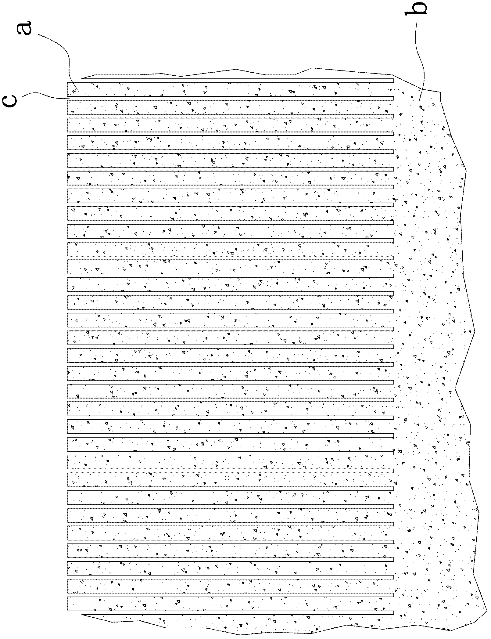
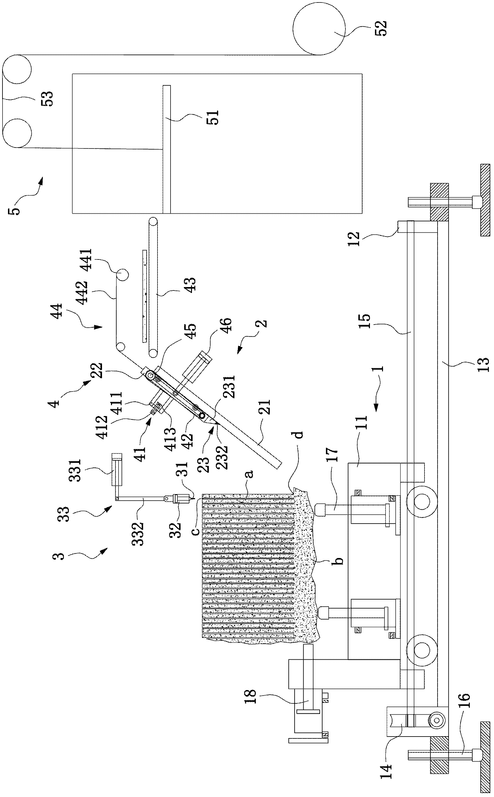
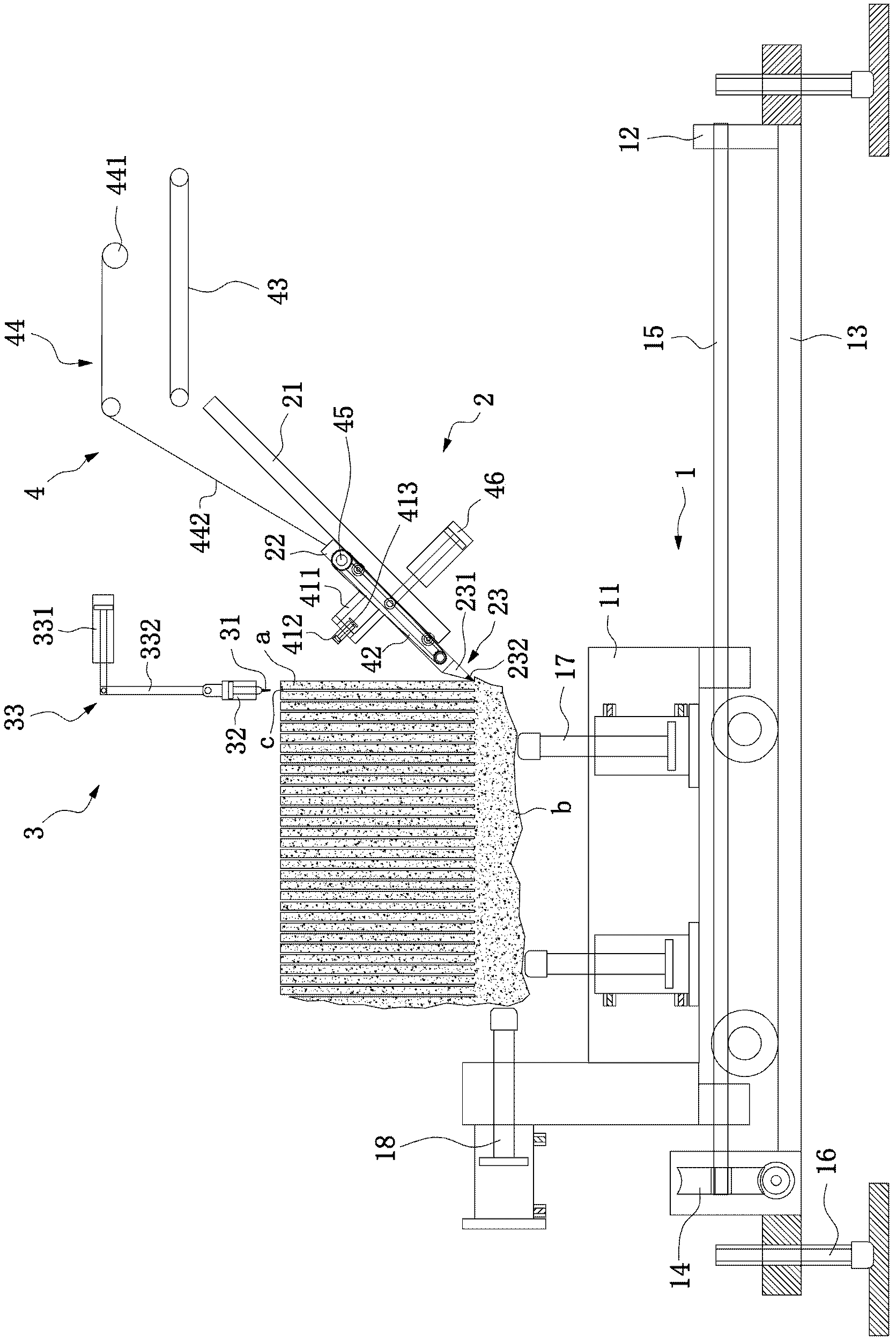
[0035] The stone unloading machine of this embodiment includes a stone transporting device 1 capable of stepping movement, an impact device 2 that hits the joint between the stone slab a and the stone main body b, and a stone slab that separates the stone slab a after the joint is injured from the stone main body b Device 3, the stone slab conveying device 4 for transporting the stone slab a and the stacking device 5 for stacking the stone slabs a, the conveying device 4 is located on the trajectory where the stone slab is detached from the stone body b and turned over after being pried by the detachment device 3, and the stacking device 5 is located at the conveying device 4 behind.

[0036] Below we describe the above devices in detail one by one:

[0037] Stone transportation device: The stone transportation device 1 is composed of a stone transportation vehicle 1...


PUM


Abstract

The invention discloses a stone board unloader, which comprises a stone transport vehicle, an impact device, a stone board separation device and a stone board conveying device, wherein the stone transport vehicle can move step by step; the impact device is used for impacting a junction part of a stone board and a stone body; the stone board separation device is used for leading the stone board after the junction part is injured to separate from the stone body; and the stone board conveying device is used for conveying the stone board. The conveying device is positioned on a turnover track after the stone board is separated from the stone body and is pried by the separation device. The unloader of the invention has the beneficial effects that after automatic equipment is utilized, the stone board unloading works including stone board knocking, stone board prying, stone board conveying, stone board stacking and the like are all mechanically performed. The stone board unloading works can be finished as long as a worker operates the equipment, so that the work is very conformable and efficient, and the working environment can be greatly improved; and moreover, the worker does not need to be in direct contact with the stone board so as to avoid the occurrence of work-related accidents.

Description

Technical field: [0001] The invention relates to a stone unloading machine. Background technique: [0002] In order to obtain natural stone slabs, workers will go to the mountain to quarry stones to obtain stone blocks, and then process the obtained blocks with saw blades, and saw a number of saw paths c on the stone blocks, so that between two saw paths Slate a is formed, but at this time, slate a is not completely separated from the stone, and the root of slate a is still connected with the main body of stone b, such as figure 1 As shown, after the sawing process is completed, it is necessary to separate and unload the stone slabs. The traditional separation and unloading of the stone slabs is done manually. The root of the joint is injured and cracked, and then the workers shake the top of the stone slab, or use tools to pry the stone slab to separate the stone slab from the main body of the stone, and finally the worker lifts the stone slab and stacks the stone slabs on...

Claims


Application Information

Patent Timeline
Patent Type & Authority Applications(China)
IPC IPC(8): B65G35/00B65G65/02
Inventor 叶大繁林铭章
Owner 佛山市新海舟科技有限公司
Why Eureka
Try Eureka