Adjustable coal mining machine rail

A shearer and adjustable technology, applied in the field of coal mine machinery and equipment, can solve the problems of resource waste, inappropriate size, waste, etc., and achieve the effect of solving supporting problems

Active Publication Date: 2012-07-04
SHANGHAI TIANDI MINING EQUIP TECH CO LTD +1
View PDF7 Cites 8 Cited by
  • Summary
  • Abstract
  • Description
  • Claims
  • Application Information

AI Technical Summary

Problems solved by technology

[0007] Due to the above two reasons, in the actual coal mining process in the mining area: in order to meet the mining needs of different coal seams, different types of shearers are required, and correspondingly need conveyors of different widths to be used together. / The distance A1 between the centers of the conveyor slots is a fixed value (the size is not suitable and cannot meet the supporting requirements), and it is often necessary to order a new conveyor; thus causing the old conveyor to be unusable and scrapped, resulting in great waste
Some mining areas adopt mandatory matching, and some size matching is often inappropriate: if the shovel spacing (the distance between the end face of the shearer drum and the shovel tip of the conveyor) is too large or too small, the overall coal loading effect is not good if it is too large , mining is difficult; if the drum is too small, it is easy to cut the shovel of the conveyor, and there are equipment safety problems. These inappropriate matching can hardly guarantee the normal mining of coal mines.
[0008] The matching problem between the shearer and the transporter has seriously affected the versatility of the equipment, and in serious cases caused a major waste of resources

Method used


Image

  • Adjustable coal mining machine rail
  • Adjustable coal mining machine rail
  • Adjustable coal mining machine rail

Examples


Embodiment 1

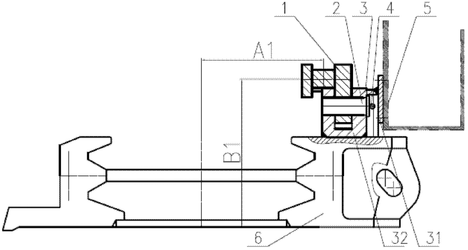
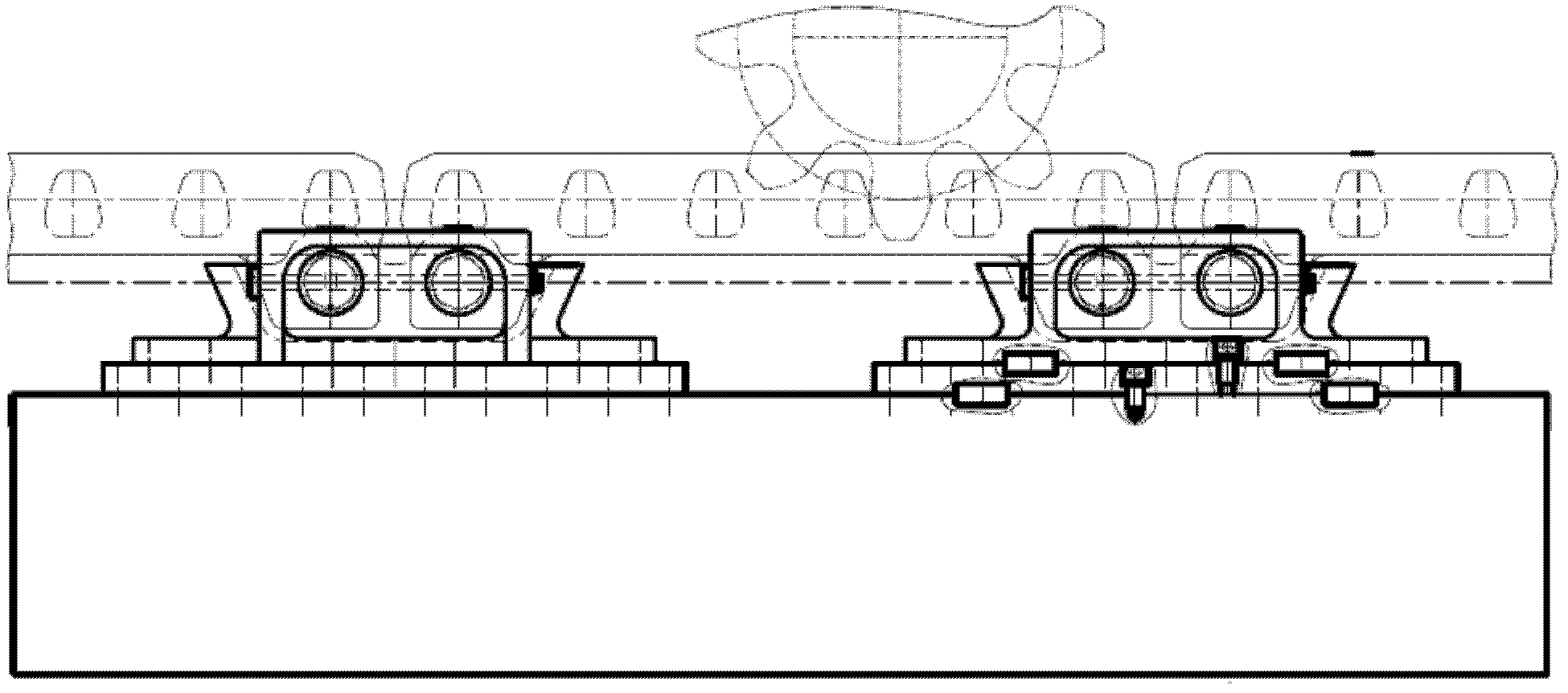
[0034] see Figure 3 to Figure 5 , the present invention discloses an adjustable shearer track, which includes: rack 1, rack fixing mechanism 2, movable rack seat 3', transition plate group 71, cable trough 5, conveyor Slot 6. In this embodiment, the rack fixing mechanism 2 is a pin. In order to prevent the pin from axially moving in series, the track of the shearer is also equipped with a stop pin 4 .

[0035] The movable rack seat 3' includes a connecting plate 31' and a movable seat 32', and the cable groove 5 is fixed on the connecting plate 31'; the rack 1 is fixed on the movable rack seat 3' through the rack fixing mechanism 2 .

[0036] The transition plate group includes one or more upper round pins 711, a transition plate 712, one or more lower round pins 713, and the upper side / lower side of the transition plate 712 is respectively provided with a plurality of upper round pins 711 / lower round pins. 713 corresponds to the hole. The movable rack seat 3' is fixed t...


PUM


Abstract

The invention discloses an adjustable coal mining machine rail, which comprises a rack rail, a rack rail fixing mechanism, a movable rack rail seat, a transition board group, a cable trough, and a transporter trough, wherein the movable rack rail seat comprises a connecting plate and a movable seat; the cable trough is fixed on the connecting plate; the transition board group comprises one or more upper round pins, a transition board, and one or more lower round pins, and multiple holes corresponding to the upper round pins/lower round pins are respectively arranged on upper side/lower side of the transition board; the movable rack rail seat is fixed to the transition board by the upper round pins and upper screws, and the transition board is fixed to the transporter trough by the lower round pins and lower screws; and the position of the movable rack rail seat can be changed by changing the holes for installation of the upper round pins on the transition board, thus the distance between the rack rail center and the transporter trough center is changed. According to the adjustable coal mining machine rail disclosed by the invention, a fixed rail for traveling of a coal mining machine on a transporter is arranged to be an adjustable rail, so that the adjustable coal mining machine rail can adapt to be matched with coal mining machines of different machine body widths for use.

Description

technical field [0001] The invention belongs to the technical field of coal mine machinery equipment, and relates to a shearer track, in particular to an adjustable shearer track. Background technique [0002] In order to adapt to the modern coal mining technology, the shearer technology is also constantly developing. The existing shearer is mainly based on the chainless traction shearer. The walking movement of the chainless traction shearer is usually: the shearer on the shearer The travel gear meshes with the shearer track—the rack of the conveyor, the travel gear of the shearer rotates, and the rack drives the shearer to move along the rack through the reaction force. [0003] Such as figure 1 , figure 2 As shown, the structure of the existing coal mining machine walking track-conveyor usually has: the rack 1 is usually fixed on the fixed rack seat 3 by the pin 2, and the fixed rack seat 3 includes a connecting plate 31 and a fixed seat 32; Connecting plate 31 is wel...

Claims


Application Information

Patent Timeline
Patent Type & Authority Applications(China)
IPC IPC(8): E01B25/02E01B25/04E01B23/02E01B23/04E21C29/22E21C35/20
Inventor 章立强曹杨唐葆霖边强魏逸王志武
Owner SHANGHAI TIANDI MINING EQUIP TECH CO LTD
Why Eureka
Try Eureka