Continuous beam falling system and continuous beam falling method
What is Al technical title?
Al technical title is built by PatSnap Al team. It summarizes the technical point description of the patent document.
A technology of falling beams and connecting sleeves, which is applied in the direction of bridges, bridge construction, erection/assembly of bridges, etc.
Active Publication Date: 2012-07-04
THE SECOND CONSTR OF CTCE GROUP
View PDF9 Cites 4 Cited by
Summary
Abstract
Description
Claims
Application Information
AI Technical Summary
This helps you quickly interpret patents by identifying the three key elements:
Problems solved by technology
Method used
Benefits of technology
Problems solved by technology
[0004] The first technical problem to be solved by the present invention is that the above-mentioned existing drop beam system takes a long time to construct, is easily deformed, has high safety risks, and cannot meet the requirements of large-span steel Requirements for box girders spanning operating lines
Method used
Image
Click on the blue label to locate the original text in one second.
Reading with bidirectional positioning of images and text.
Examples
Embodiment 1
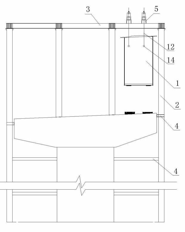
[0033] During use, use the continuous beam drop system of this embodiment to complete the drop beam operation through the following steps:
[0034] The first step is to knock the first set of clips one by one between the anchor hole of the lower tool and the steel strand to clamp the steel strand;
[0035] The second step is to control the continuous jack to rise through the hydraulic system;
[0036] The third step is to knock the second set of clips one by one between the anchor hole of the upper tool and the steel strand to clamp the steel strand;
[0037] The fourth step is to use the pliers to pick out the clips of the lower tool anchor one by one;
[0038] The fifth step is to control the drop of the continuous jack through the hydraulic system, and the upper tool anchor with the drop of the jack drives the steel strand and the hoisted beam down;
[0039] Repeat the above steps until the hoisted beam is dropped to the desired place.
[0040] Embodiment two
Embodiment 2
[0042] Embodiment Three
Embodiment 3
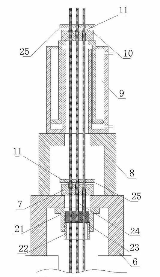
[0044] When in use, use the continuous beam drop system of this embodiment to complete the drop beam operation through the following steps:
[0045] The first step is to screw down the movable sleeve of the anchor retractor, and make the first group of clips clamp the steel strand by hitting the reset plate at the top of the anchor of the lower tool;
[0046] The second step is to control the continuous jack to rise through the hydraulic system;
[0047] The third step is to make the second set of clips clamp the steel strand by knocking the reset plate at the top of the upper tool anchor;
[0048] The fourth step is to screw up the movable sleeve of the anchor retractor to drive the push plate to move, and the push tube on the push plate pushes out the first set of clips to complete the anchor removal of the tool;
[0049] The fifth step is to control the drop of the continuous jack through the hydraulic system, so that the upper tool anchor drives the steel strand and the h...
PUM
Abstract
The invention relates to a continuous beam falling system and a continuous beam falling method, and belongs to the technical field of construction equipment and methods. The continuous beam falling system comprises a gantry bracket and a continuous beam falling mechanism arranged on the top of the gantry bracket, wherein the continuous beam falling mechanism comprises a lower supporting foot connected with the top of the gantry bracket, a lower tool anchor and an upper supporting foot which are fixedly connected to the top of the lower supporting foot, and a continuous jack fixedly connected to the top of the upper supporting foot; an upper tool anchor is fixedly connected to the top of the continuous jack; clamping sheets are arranged in through holes of the upper tool anchor and the lower tool anchor; and steel stranded wires penetrate through the clamping sheets. The continuous beam falling method comprises the following steps of: anchoring the steel stranded wires in turn by using the upper tool anchor and the lower tool anchor, withdrawing the anchors, and descending and ascending the continuous jack. A hoisted beam can continuously fall stably. The invention has the advantages that: the system and the method are safe and reliable, and time and labor are saved.
Description
technical field [0001] The invention relates to a continuous beam drop system and a continuous beam drop method using the continuous beam drop system, belonging to the technical field of construction equipment and methods. Background technique [0002] In the construction of elevated highways, it is often encountered that the crossing of the operating lines, such as crossing the high-speed rail, the catenary above the high-speed rail must leave a safe distance from the bracket at the bottom of the beam during construction, so it is necessary to use the bracket to hold the beam Assemble at a position higher than the pier, remove the support after the assembly is completed, and then use equipment to drop the beam onto the pier. [0003] After searching, the Chinese invention patent CN200710302498.7 discloses a large-scale box girder hoisting device and its method. Using this method, the girder needs to be made of a joist, and the special hoisting system adopts multiple lifting...
Claims
Application Information
Patent Timeline
Application Date:The date an application was filed.
Publication Date:The date a patent or application was officially published.
First Publication Date:The earliest publication date of a patent with the same application number.
Issue Date:Publication date of the patent grant document.
PCT Entry Date:The Entry date of PCT National Phase.
Estimated Expiry Date:The statutory expiry date of a patent right according to the Patent Law, and it is the longest term of protection that the patent right can achieve without the termination of the patent right due to other reasons(Term extension factor has been taken into account ).
Invalid Date:Actual expiry date is based on effective date or publication date of legal transaction data of invalid patent.