
Friction-metallic yielding energy consumption combined control damping device applied to shear wall connecting beam and control method thereof

A shock absorption device and friction energy consumption technology, which is applied in the direction of anti-seismic and building components to achieve the effect of improving the anti-seismic effect, clear working principle and good application prospect.

Inactive Publication Date: 2012-07-04
DALIAN UNIV OF TECH
View PDF7 Cites 17 Cited by
  • Summary
  • Abstract
  • Description
  • Claims
  • Application Information

AI Technical Summary

Problems solved by technology

Structural ductility design requires following the principles of "strong limbs and weak beams" and "strong shear and weak bending", but there are often contradictions when ensuring that the stiffness and ductility of coupling beams meet the design requirements at the same time

Method used


Image

  • Friction-metallic yielding energy consumption combined control damping device applied to shear wall connecting beam and control method thereof
  • Friction-metallic yielding energy consumption combined control damping device applied to shear wall connecting beam and control method thereof
  • Friction-metallic yielding energy consumption combined control damping device applied to shear wall connecting beam and control method thereof

Examples


Embodiment 1

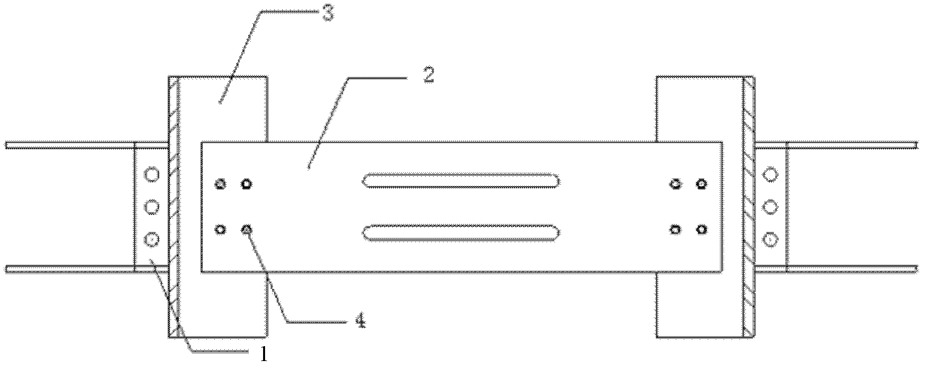
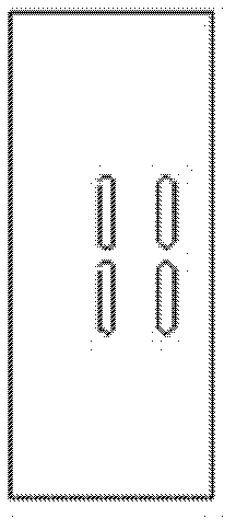
[0021] First, pre-cast the embedded area 1 and the shear wall together: weld the friction steel plate 3 and the embedded area 1 together; open bolt holes on the metal yield damper 2, and open holes for the bolts to slide on the friction steel plate 3 Groove; the metal yield damper 2 and the friction steel plate 3 are connected together by bolts, and the metal yield damper and the friction steel plate are connected in series to form a whole as a shock absorbing device.

Embodiment 2

[0023] Under the action of small earthquakes, the main structure is in an elastic working state, and the joint control device works well without damage. Among them, the friction working area of ​​the joint control device does not enter the slipping stage, and the mild steel damper is in the elastic deformation stage. Under moderate earthquakes, the main structure is in an elastic working state, and the joint-control damper slips in the frictional working area to dissipate structural energy, and the mild steel damper is still in the elastic deformation stage. After the earthquake, carry out necessary overhaul and reset on the device, and it can continue to be used after maintenance. Under the action of a large earthquake, some components in the main structure enter the elastic-plastic stage, resulting in limited damage, but the structural integrity is still intact.


PUM


Abstract

The invention discloses a damping device and a using method of the damping device, in particular relates to a friction-metallic yielding energy consumption combined control damping device applied to a shear wall connecting beam and a using and installation method of the damping device, belonging to the technical field of structural vibration control in civil engineering. The invention relates to a control method for combining a metallic yielding damper and a metal friction damper to improve an energy consumption vibration-damping performance of a damper, and the damping device mainly consists of a metal friction energy consumption area, a soft steel yielding energy consumption area and a built-in area connected with a shear wall. The purpose of energy consumption in a staging manner is achieved by soft steel yielding energy consumption and steel plate friction energy consumption, and the magnitude of pretightening force that the friction damper is connected with a bolt is adjusted to enable the combined control damper to have an adjusting function. The device and the method in the invention can be applied to a high-rise coupled shear wall structure to attach or replace the connecting beam, so as to improve the energy consumption performance and improve the structural seismic-resisting effect. The friction-metallic yielding energy consumption combined control damping device is convenient to manufacture, and has accurate working principle and good application prospect.

Description

technical field [0001] The invention belongs to the technical field of vibration control of civil engineering structures, and relates to a practical energy dissipation damping device in the field of civil engineering, in particular to a friction-metal yield energy dissipation joint control damping applied to shear wall coupling beams device. Background technique [0002] The traditional anti-seismic design is to resist the earthquake action by enhancing the anti-seismic performance of the structure itself. It uses the structure itself to store and consume seismic energy to meet the anti-seismic fortification goal of the structure, that is, to achieve "not damaged by small earthquakes, repairable by moderate earthquakes, and not collapsed by large earthquakes." ". Combined shear wall structure is a commonly used structural form of high-rise structures. Its working mechanism and failure mode under earthquake action are closely related to the stiffness and bearing capacity of ...

Claims


Application Information

Patent Timeline
Patent Type & Authority Applications(China)
IPC IPC(8): E04B1/98
Inventor 欧进萍张喆何政
Owner DALIAN UNIV OF TECH
Learn More