
Trough-type solar energy comprehensive utilization system

A trough solar energy and solar energy technology, which is applied in the field of solar energy comprehensive utilization system, can solve the problems of design, manufacturing, restricting the application of trough solar power generation system, difficult commercial operation and industrialization development, etc.

Inactive Publication Date: 2012-07-04
孟忠阳
View PDF3 Cites 4 Cited by
  • Summary
  • Abstract
  • Description
  • Claims
  • Application Information

AI Technical Summary

Problems solved by technology

Moreover, the focal line of the parabolic mirror (such as a Fresnel lens) of the existing trough solar power generation system moves in space with the movement of the sun, so that the power generation system also moves in space with the focal line; system, water pipelines are difficult to move in a wide range of space, which brings difficulties to design and manufacture
The above reasons limit the application of trough solar power generation system
Although some demonstration projects of trough solar power generation systems have been successfully operated and have initially possessed the characteristics of commercial operation, due to the limitations of the above reasons, it is difficult to develop to a deeper level of commercial operation and industrialization

Method used


Image

  • Trough-type solar energy comprehensive utilization system
  • Trough-type solar energy comprehensive utilization system
  • Trough-type solar energy comprehensive utilization system

Examples


Embodiment Construction

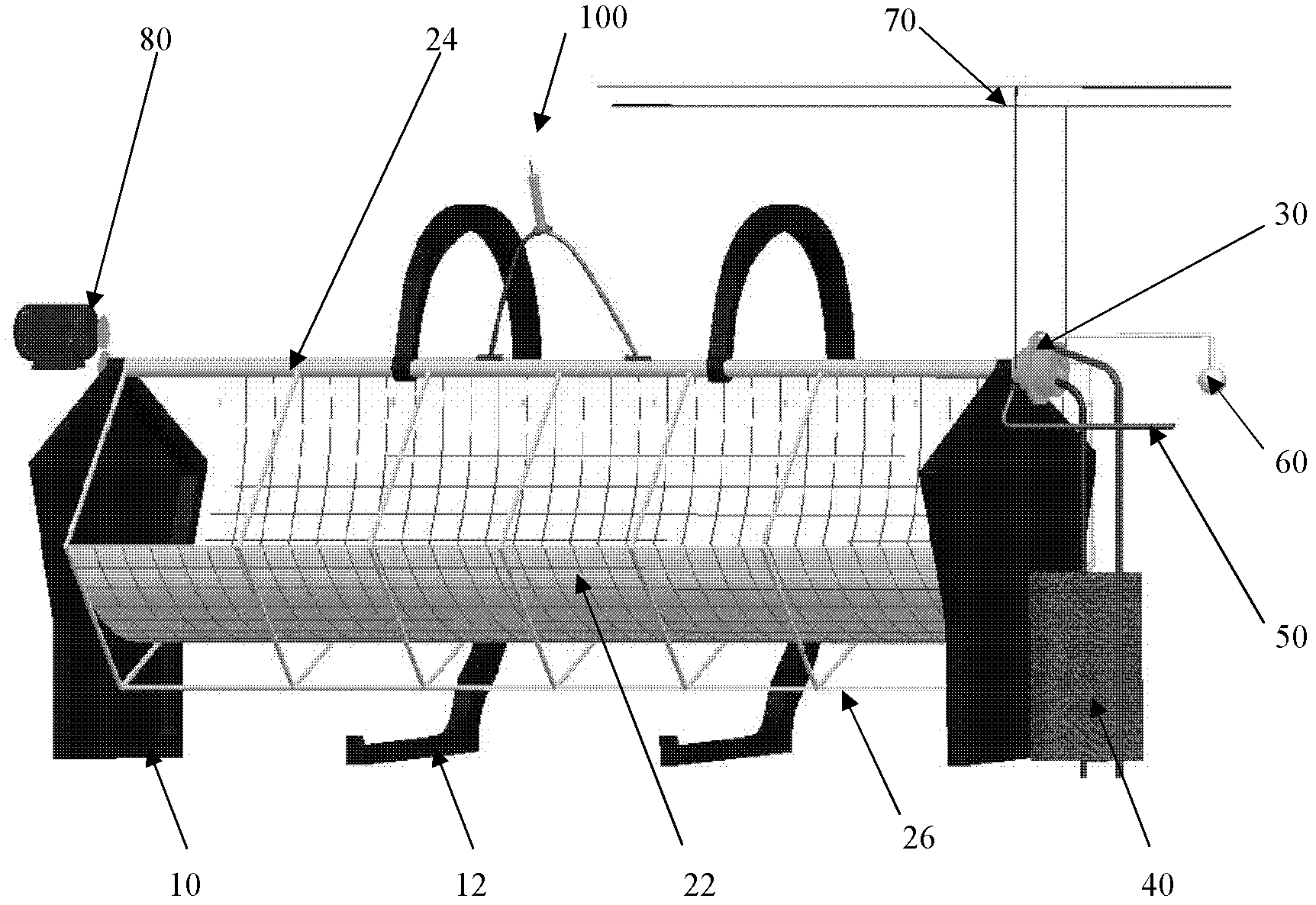
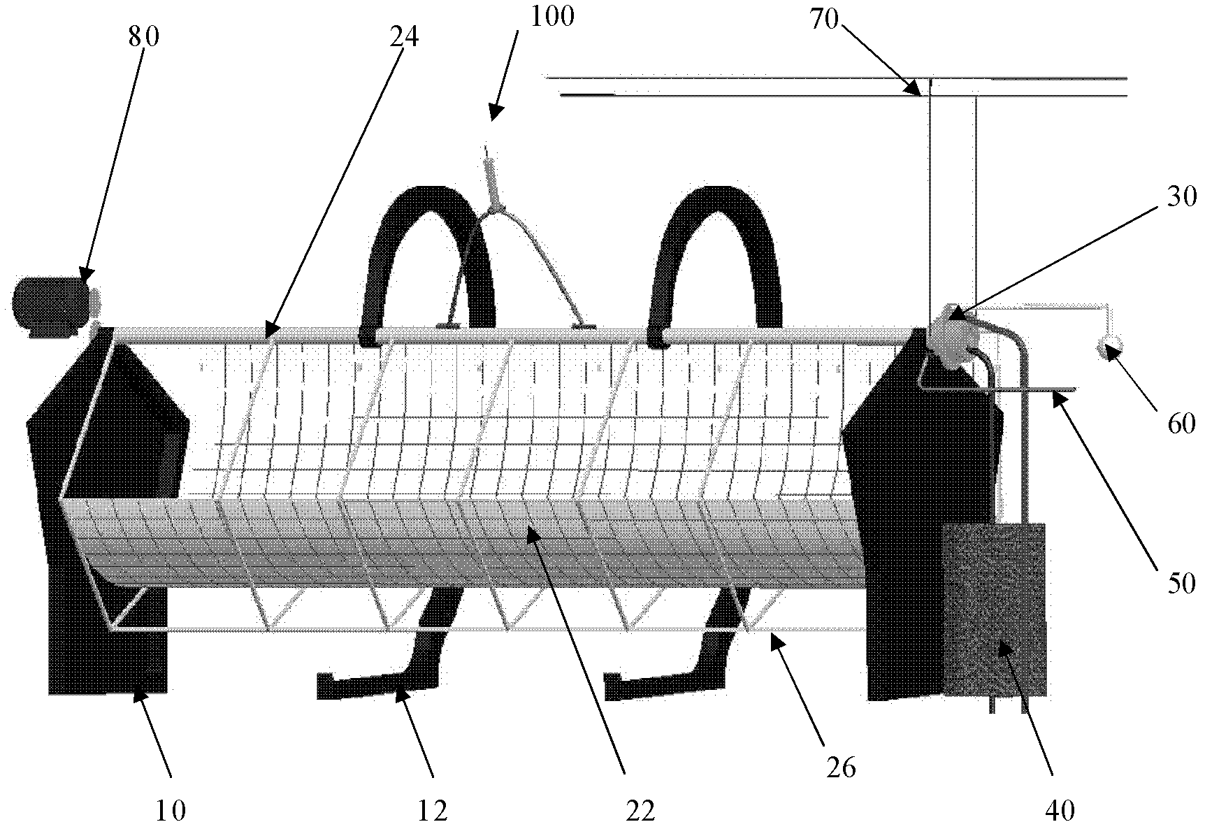
[0022] The trough solar comprehensive utilization system of the present invention will be described in detail below in conjunction with the accompanying drawings.

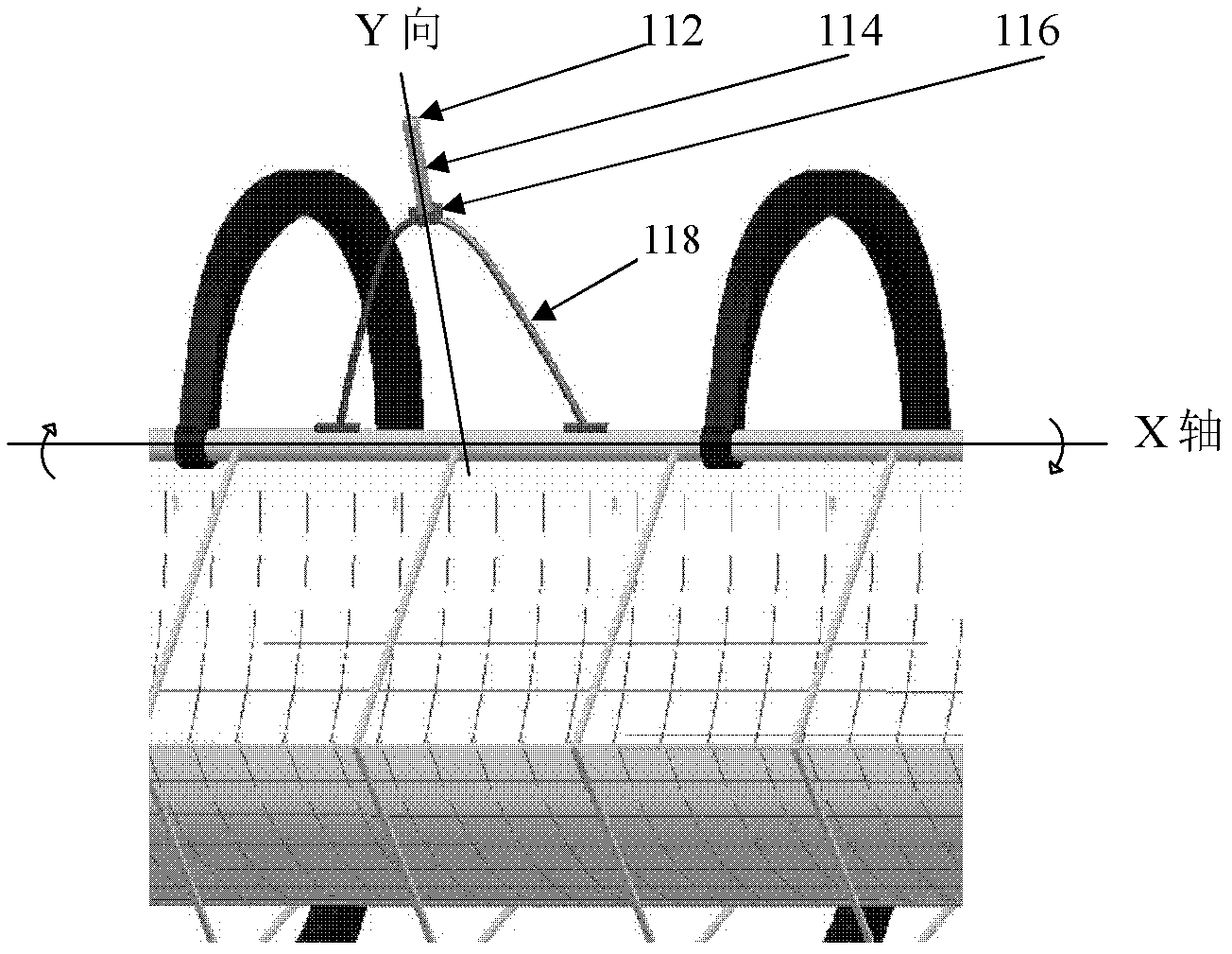
[0023] figure 1 A preferred embodiment of the trough solar comprehensive utilization system of the present invention is shown. The system includes a fuselage 10, a solar energy receiving and converting device (including a mirror 22) fixed to the fuselage 10, a power generation system 30 connected to the solar receiving and converting device, and an X-axis rotary drive installed at one end of the solar receiving and converting device. System 80, and a tracking drive control system 100 installed on the solar energy receiving and converting device. The tracking transmission control system 100 includes a sun tracking guide column 114 perpendicular to the mirror (lens or reflector) 22 . Driven by the X-axis rotation drive system 80 and controlled by the tracking drive control system 100 , the sun tracking guide column...


PUM


Abstract

The invention discloses a trough-type solar energy comprehensive utilization system, which includes a machine body, a solar energy receiving and transforming device fixed to the machine body, a generating system connected to the solar energy receiving and transforming device and fixed to the machine body, a rotation driving system mounted at one end of the solar energy receiving and transforming device, and a tracking transmission control system mounted on the solar energy receiving and transforming device, wherein the solar energy receiving and transforming device is used for receiving sunlight and transferring the sunlight into heat energy, and includes a face mirror; the generating system does work and generates power by utilizing the heat energy transformed by the solar energy receiving and transforming device; the rotation driving system is used for driving the face mirror; and the tracking transmission control system is used for driving the rotation driving system to rotate through light signals about sun positions, and maximizing the capability of receiving sunlight through driving the face mirror. The system further includes a fuel system used for enabling the generating system to work continuously under insufficient light, as well as a natural light illumination system and a cooling water circulating system, therefore, the comprehensive solar energy utilization system is formed.

Description

technical field [0001] The invention relates to the technical fields of solar energy application technology, Stirling power generation power system and the like, and is a comprehensive utilization system of solar energy. In addition, a gas power system can also be installed, so that the two energy sources of solar energy and gas can complement each other to drive the Stirling power generation system to generate electricity. The heat generated by the Stirling power generation system heats and cools water, which can be directly used to provide domestic hot water or for cooling and heating of air-conditioning systems; the concentrated solar energy is transmitted through optical fibers and directly used for natural lighting without conversion. Background technique [0002] Solar energy has been widely used in photovoltaic power generation, trough solar thermal power generation, heating system and natural lighting. The current various solar energy utilization systems cannot orga...

Claims


Application Information

Patent Timeline
IPC IPC(8): F03G6/06F02G1/043F24J2/00F24J2/08F24J2/10F24S23/30F24S23/70
CPCY02E10/46
Inventor 孟忠阳任前卯
Owner 孟忠阳
Learn More