Fan shaft sleeve

A fan shaft and shaft hole technology, which is applied in the field of fan shaft sleeves, can solve the problems of the shaft center being stuck, unable to rotate, and shorten the service life, so as to achieve the effects of increasing service life, improving assembly efficiency, and reducing operating noise

Inactive Publication Date: 2012-07-04
常熟市宏达印染机械有限公司
View PDF0 Cites 0 Cited by
  • Summary
  • Abstract
  • Description
  • Claims
  • Application Information

AI Technical Summary

Problems solved by technology

When the circuit board is energized, the stator is excited to generate a magnetic force on the rotor, and then the rotor is driven to rotate, so that the fan blades rotate to generate airflow and achieve the cooling effect on the components. However, because the axis rotates in the sleeve, the axis and There is no lubrication between th

Method used


Image

  • Fan shaft sleeve
  • Fan shaft sleeve

Examples


Embodiment Construction

[0014] The present invention will now be described in further detail in conjunction with the accompanying drawings and preferred embodiments. These drawings are all simplified schematic diagrams, which only illustrate the basic structure of the present invention in a schematic manner, so they only show the configurations related to the present invention.

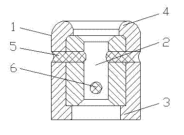
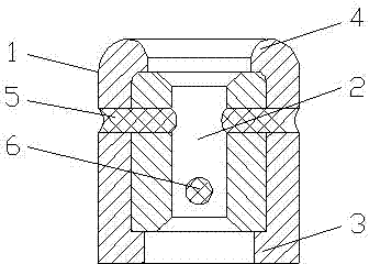
[0015] Such as figure 1 As shown, a fan bushing includes a cylindrical body 1, and the cylindrical body is provided with a shaft hole 2, a stopper 3, a fixing portion 4 and an oil storage hole, and the oil storage hole includes a main oil storage hole 5 and a secondary oil storage hole. The oil storage hole 6, the main oil storage hole 5 and the auxiliary oil storage hole 6 pass through the cylinder body 1, the main oil storage hole 5 and the auxiliary oil storage hole 6 communicate with the shaft hole 2, and the main oil storage hole 5 and the auxiliary oil storage hole 6 are arranged non-parallel, the stop part 3 is arran...


PUM


Abstract

The invention relates to a fan shaft sleeve, which comprises a drum body, wherein the drum body is provided with a shaft hole, a stopping part, a fixing part and an oil storage hole; the oil storage hole comprises a main oil storage hole and an auxiliary oil storage hole; the main oil storage hole and the auxiliary oil storage hole penetrate through the drum body, are communicated with the shaft hole, and are arranged in a non-parallel manner; the stopping part is arranged at the bottom of the drum body; and the fixing part is arranged at the top of the drum body. By adopting the fan shaft sleeve provided by the invention, the friction between the shaft center and the shaft sleeve is reduced, the service life is prolonged and the assembly efficiency is increased.

Description

technical field [0001] The invention relates to a shaft sleeve, in particular to a fan shaft sleeve. Background technique [0002] The cooling fan can dissipate the heat energy generated by electronic and motor components to achieve heat dissipation and cooling, avoiding damage to components due to high temperature and affecting operation, thereby protecting components and prolonging component life. Today's computer hosts and video recorders Or copiers are equipped with cooling fans, and current cooling fans mostly use brushless DC motors as drive components. The composition of the existing fan mainly includes a frame, a shaft sleeve, a shaft center, a retaining ring, fan blades, a circuit board, a stator, and a rotor. Made of metal, it has a strong structure and wear resistance. The shaft center is set in the shaft sleeve. One end goes out of the shaft sleeve and is fastened with a buckle ring, and the other end goes out of the shaft sleeve and bites the fan blade. The fan...

Claims


Application Information

Patent Timeline
IPC IPC(8): F04D29/05
Inventor 周国东
Owner 常熟市宏达印染机械有限公司
Why Eureka
Try Eureka