Rolling bearing arrangement structure resistant to external impact

A technology for arranging structures and rolling bearings, applied in the directions of bearing components, shafts and bearings, and rigid supports of bearing components, can solve the problems of inability to run the shafting, transmission accuracy, reduction, and short service life, and achieve simple installation, convenient use, The effect of improving the service life

Pending Publication Date: 2021-01-22
中国船舶重工集团公司第七0三研究所
View PDF0 Cites 0 Cited by
  • Summary
  • Abstract
  • Description
  • Claims
  • Application Information

AI Technical Summary

Problems solved by technology

[0004] The present invention solves the problem that the existing bearing arrangement structure is subject to unstable radial and axial loads caused by the deformation of the external elastic coupling at the same time during operation. Reduced, and the problem of short service life, and propose a rolling bearing arrangement structure that resists external impact

Method used


Image

  • Rolling bearing arrangement structure resistant to external impact
  • Rolling bearing arrangement structure resistant to external impact
  • Rolling bearing arrangement structure resistant to external impact

Examples


specific Embodiment approach 1

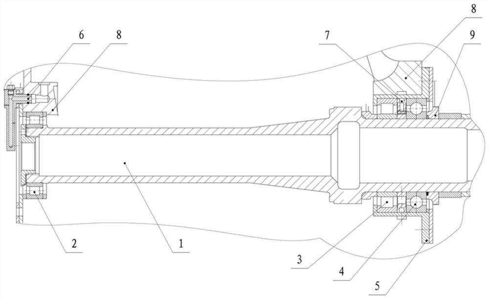
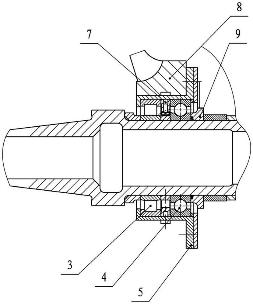
[0020] Specific implementation mode one: combine Figure 1 to Figure 3 Describe this embodiment. The rolling bearing arrangement structure against external impact described in this embodiment includes a shafting 1, a No. 1 cylindrical roller bearing 2, a No. 2 cylindrical roller bearing 3, a four-point contact ball bearing 4, and a bearing bushing Cover 5, box body 8 and spacer ring 9;

[0021] There are through holes on both sides of the box body 8, and the two through holes are arranged symmetrically. A No. 1 cylindrical roller bearing 2 is embedded in the through hole on one side of the box body 8, and a bearing is embedded in the through hole on the other side of the box body 8. Bushing 5, the inside of the bearing bushing 5 is evenly embedded with a No. 2 cylindrical roller bearing 3 and a four-point contact ball bearing 4 along the axial direction, and one end of the shafting 1 is connected to the inner ring of the No. 1 cylindrical roller bearing 2 Fixed connection, th...

specific Embodiment approach 2

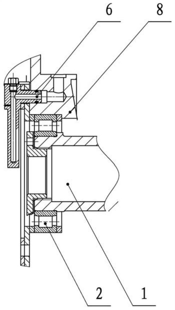
[0023] Specific implementation mode two: combination figure 2 and image 3 Describe this embodiment. This embodiment is a further limitation on the bearing arrangement described in the first specific embodiment. The rolling bearing arrangement described in this embodiment is resistant to external impact. The bearing arrangement also includes a No. 6 fuel injector 6 and No. 2 fuel injector 7; an oil passage is provided on both sides of the upper surface of the box body 8, and No. 1 fuel injector 6 is provided on one side of the box body 8, and No. 1 fuel injector 6 and The oil passage is connected, and the other side of the box body 8 is provided with the No. 2 fuel injector 7, and the No. 2 fuel injector 7 is connected with the oil passage;

[0024] In this specific embodiment, two ends of the box body 8 are respectively provided with an oil spray nozzle, and when the shafting 1 rotates at high speed, the bearings are lubricated through the oil spray nozzles at both ends, wh...

specific Embodiment approach 3

[0025] Specific implementation mode three: combination figure 2 Describe this embodiment. This embodiment is a further limitation on the bearing arrangement described in Embodiment 2. In this embodiment, a rolling bearing arrangement that resists external impacts, the No. 1 oil injector 6 Fixed connection with one side of the box body 8 by bolts;

[0026] In this specific embodiment, the No. 1 fuel injector 6 is fixedly connected to one side of the casing 8 through bolts to improve stability.


PUM


Abstract

The invention discloses a rolling bearing arrangement structure resistant to external impact, and relates to the field of mechanical structure connection modes. The problems that an existing bearing arrangement structure can bear unstable radial and axial loads generated by deformation of an external elastic coupler at the same time in the operation process, and when external impact is large, a shaft system cannot operate or the transmission precision is reduced, and the service life is short are solved. A first cylindrical roller bearing is embedded in a through hole in one side of a box body, a bearing bush is embedded in a through hole in the other side of the box body, a second cylindrical roller bearing and a four-point contact ball bearing are evenly embedded in the bearing bush in the axis direction, one end of the shaft system is fixedly connected with an inner ring of the first cylindrical roller bearing, the other end of the shaft system sequentially penetrates through an inner ring of the second cylindrical roller bearing, an inner ring of the four-point contact ball bearing and a distance ring to be rotationally connected with the box body, and the distance ring is fixedly connected with the other side face of the box body through a bolt. The invention is suitable for the rolling bearing arrangement structure of the high-speed rotating shaft system.

Description

technical field [0001] The invention relates to the field of mechanical structure connection methods, in particular to a rolling bearing arrangement structure resistant to external impact. Background technique [0002] Rolling bearing is a common shaft support part, which is widely used in industrial production. According to its load bearing characteristics, it can be mainly divided into cylindrical roller bearings that only bear radial loads, four-point contact ball bearings that bear axial loads and Deep groove ball bearings that can bear both radial and axial loads. Usually, when the shaft system is subjected to both radial load and axial load, an arrangement of two deep groove ball bearings is adopted, but the limit speed of deep groove ball bearings is usually low (<5000rmin). The input shaft speed of a certain product exceeds 8000r / min. During operation, it will be subjected to unstable radial and axial loads caused by the deformation of the external elastic coupli...

Claims


Application Information

Patent Timeline
Patent Type & Authority Applications(China)
IPC IPC(8): F16C35/07F16N7/00
CPCF16C35/07F16N7/00F16N2210/14
Inventor 武毅杨龙胡朝阳陈营利汤鱼
Owner 中国船舶重工集团公司第七0三研究所
Why Eureka
Try Eureka