Eureka AIR delivers breakthrough ideas for toughest innovation challenges, trusted by R&D personnel around the world.

Box-type protective atmosphere heat treatment furnace

A protective atmosphere and heat treatment furnace technology, which is applied in the field of box-type protective atmosphere heat treatment furnaces, can solve the problems of insufficient sealing performance and poor compression of sealing rings, etc., to reduce rotation resistance, reduce rotation resistance, and prevent wear Effect

Inactive Publication Date: 2013-07-24
海盐华辰工业炉有限公司
View PDF1 Cites 0 Cited by
  • Summary
  • Abstract
  • Description
  • Claims
  • Application Information

AI Technical Summary

Problems solved by technology

[0005] Although the furnace door sealing device suitable for a box-type heat treatment furnace adopts an inner and outer double-layer sealing structure, it can meet the sealing requirements of the heat treatment furnace to a certain extent, but since the furnace door rollers have to roll between the vertical guide groove and the horizontal guide groove , there must be a certain gap between the furnace door roller and the guide groove, which leads to the inability of the inner and outer sealing knives to press the sealing rings in the inner and outer sealing grooves well; There is also a gap necessary for sliding up and down, resulting in insufficient sealing performance

Method used


Image

  • Box-type protective atmosphere heat treatment furnace
  • Box-type protective atmosphere heat treatment furnace
  • Box-type protective atmosphere heat treatment furnace

Examples


Embodiment Construction

[0039] The specific implementation manners of the present invention will be described in detail below in conjunction with the accompanying drawings.

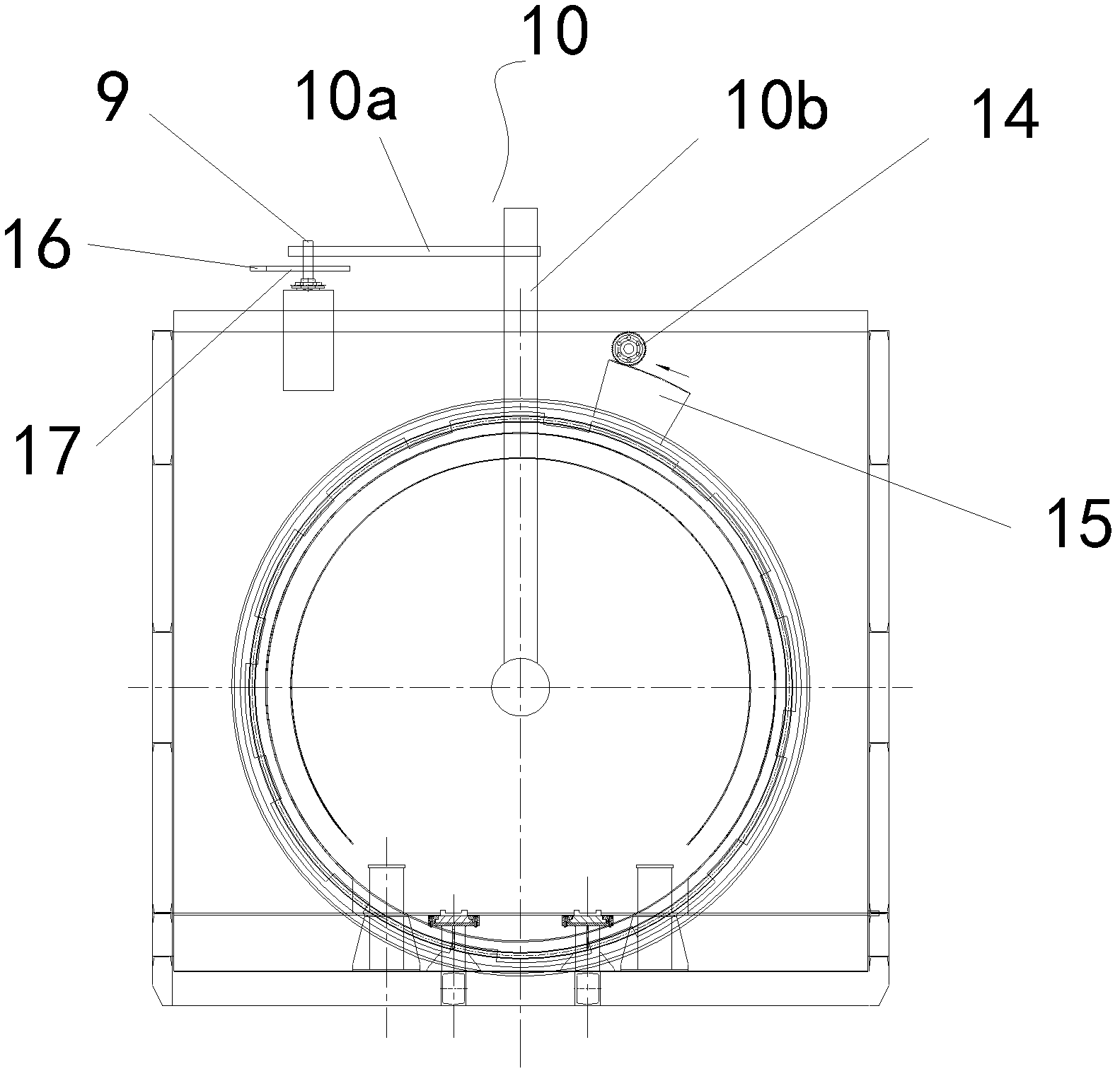
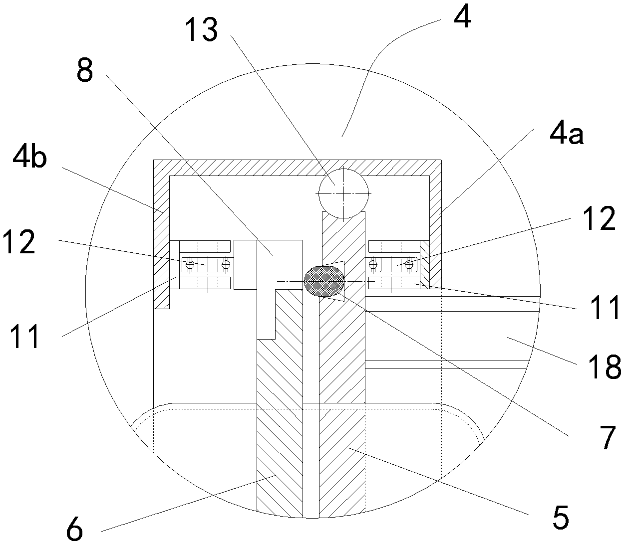
[0040] Such as figure 1 Shown is a schematic structural diagram of an embodiment of a box-type protective atmosphere heat treatment furnace of the present invention. The box-type protective atmosphere heat treatment furnace of this embodiment includes a furnace body 1 , a furnace door 2 and a charging device 3 , and a furnace door sealing device and a furnace door opening device are provided between the furnace body 1 and the furnace door 2 . Such as image 3 As shown, the furnace door sealing device includes a compression ring 4, a driving device for driving the rotation of the compression ring 4, a furnace door flange 5 and a furnace door flange respectively arranged on the furnace body 1 and the furnace door 2. The sealing flange 6, and the sealing ring 7 arranged between the furnace door flange 5 and the sealing flange 6, ...


PUM


Abstract

The invention discloses a box-type protective atmosphere heat treatment furnace which comprises a furnace body, a furnace door and a charging device. A furnace door sealing device and a furnace door opening device are arranged between the furnace body and the furnace door. The furnace door sealing device comprises a compressing ring, a driving device, a furnace door flange, a sealing flange and asealing ring, wherein the furnace door flange and the sealing flange are respectively and correspondingly arranged on the furnace body and the furnace door; and the sealing ring is arranged between the furnace door flange and the sealing flange. The compressing ring is sleeved on the furnace door flange. An inner flange and a compressing flange are arranged on the compressing ring. A compressing wedge block matched with the compressing flange is arranged on the sealing flange. A compressing inclined plane is arranged on the compressing wedge block. The furnace door opening device comprises a furnace door supporting rod, a rotary lever and a transmission mechanism, wherein the furnace door supporting rod is rotationally arranged on the furnace body; the rotary lever is respectively connected with the furnace door supporting rod and the furnace door; and the transmission mechanism is used for driving the rotary lever to rotate and hoisting the furnace door to one side of the furnace body. Not only does the box-type protective atmosphere heat treatment furnace have better sealing performance and the protective atmosphere with higher class can be used in the furnace, but also the furnace door is convenient to open and close and the box-type protective atmosphere heat treatment furnace is convenient to implement.

Description

technical field [0001] The invention relates to a heat treatment furnace, in particular to a box-type protective atmosphere heat treatment furnace with good sealing performance and capable of using a higher-grade protective atmosphere. Background technique [0002] Heat treatment furnace is a general term for industrial furnaces used to perform various metal heat treatments on metal workpieces. Heat treatment furnaces can use various types of heating furnaces, but stricter control of furnace temperature and furnace atmosphere is required. The box-type heat treatment furnace is a periodic operation furnace widely used in metal heat treatment. In the process of heat treatment in the box-type heat treatment furnace, the poor sealing of the furnace door will not only easily cause the heat in the furnace to be lost from the furnace door. The entire heat treatment cycle time is lengthened, resulting in waste of energy, and the temperature of the material near the furnace door ofte...

Claims


Application Information

Patent Timeline
Patent Type & Authority Patents(China)
IPC IPC(8): F27B3/02F27B3/10F27B5/04F27D1/18F27D7/06C21D1/00C21D1/26
Inventor 于云飞
Owner 海盐华辰工业炉有限公司
Why Eureka
Eureka Blog
Learn More