

Calibrating device for eddy sensor
An eddy current sensor and calibration device technology is applied in the field of detection technology and sensors to achieve the effects of improving test accuracy, improving adaptability and accuracy, and reducing influence
- Summary
- Abstract
- Description
- Claims
- Application Information
AI Technical Summary
Problems solved by technology
Method used
Image

Examples
Embodiment Construction
[0019] The present invention will be described in detail below in conjunction with the accompanying drawings.
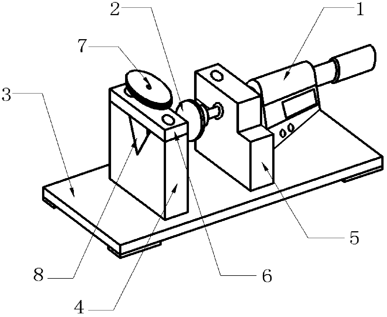
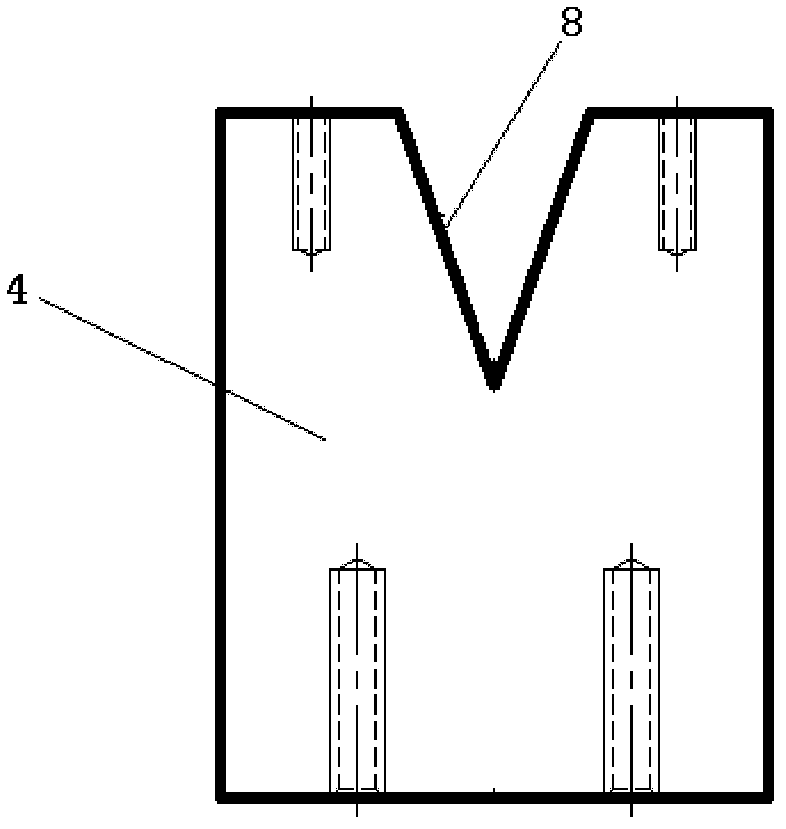
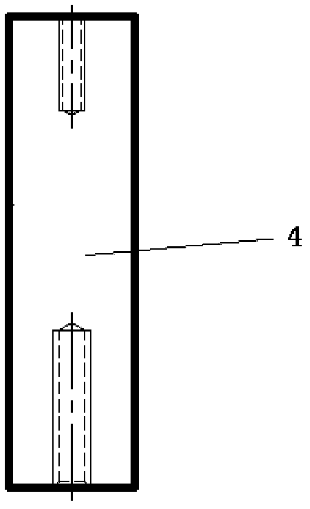
[0020] refer to figure 1 , a kind of eddy current sensor calibration device, comprises micrometer 1, and micrometer 1 is fixed on platform base 3 through micrometer support 5, and micrometer measuring rod moves freely according to specific reference value, and the moving amount utilizes digital display reading head to read, through controllable The fine-tuning device can accurately move the probe distance, and fix the distance between the sensor under test and the test flat head 2 to achieve the purpose of calibration. Refer to Figure 3a and Figure 3b , the test flat head 2 is connected with the micrometer 1 through screws, the sensor bracket 4 is fixed on the bench base 3, the sensor positioning block 6 and the positioning screw 7 are fixed on the sensor bracket 4, and the axis of the sensor bracket 4 and the micrometer bracket 5 are on the same line.
[0021] r...
PUM
 Abstract
Description
Claims
Application Information