Rapidly converged scene-based non-uniformity correction method

A non-uniformity correction, fast convergence technology, applied in radiation pyrometry, optical radiation measurement, instruments, etc., can solve problems such as staying in the laboratory stage, target search and tracking system performance limitations, etc., to avoid ghost effects , to prevent parameter error update, the effect of high correction accuracy

Inactive Publication Date: 2014-04-02
NANJING UNIV OF SCI & TECH
View PDF4 Cites 0 Cited by
  • Summary
  • Abstract
  • Description
  • Claims
  • Application Information

AI Technical Summary

Problems solved by technology

However, most of the current infrared imaging systems only use calibration-based non-uniformity correction methods.
The parameter drift of the non-uniformity of the infrared imaging system and the operational complexity of the traditional calibration-based non-uniformity correction method make its performance in some fields, such as airborne, missile-borne, field exploration operations, target search and tracking systems severely restricted
However, the current scene-based non-uniformity correction technology mostly stays in the laboratory stage due to the above-mentioned many limiting factors.

Method used


Image

  • Rapidly converged scene-based non-uniformity correction method
  • Rapidly converged scene-based non-uniformity correction method
  • Rapidly converged scene-based non-uniformity correction method

Examples


Embodiment Construction

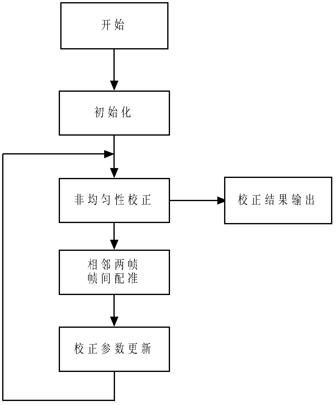
[0021] Combine figure 1 , The fast convergence correction method based on scene non-uniformity of the present invention, the steps are as follows:

[0022] Step 1: Initialization: Acquire a frame of uncorrected original image and set the gain correction parameter and offset correction parameter in the first frame to all 1 and all 0.

[0023] Acquire a frame of uncorrected original image, denoted as Y 1 (i,j). Gain correction parameter g when initializing the first frame 1 (i,j) and offset correction parameter o 1 (i, j) are respectively g 1 (i,j)=1,o 1 (i,j)=0. Since the gain correction parameter g 1 (i,j) are all 1, offset correction parameter o 1 (i, j) are all 0, which is equivalent to not performing non-uniformity correction.

[0024] Step 2: Non-uniformity correction: read in a new uncorrected original image, and use the current non-uniformity correction parameters to perform non-uniformity correction together with the previous uncorrected original image.

[0025] Read in a new ...


PUM


Abstract

The invention discloses a rapidly converged scene-based non-uniformity correction method, wherein the aim of non-uniformity correction is achieved by minimizing interframe registration error of two adjacent images. The method mainly comprises the following steps of: initializing gain and offset correction parameters and acquiring an uncorrected original image; acquiring a new uncorrected original image, and carrying out non-uniformity correction on the new uncorrected original image and the previous uncorrected original image by utilizing the current non-uniformity correction parameters; obtaining relative displacement, scene correlation coefficient and interframe registration error of two corrected images by utilizing an original point masking phase correlation method; and updating correction parameters along the negative gradient direction by adopting a steepest descent method. The method disclosed by the invention has the advantages of high correction accuracy, fast convergence speed, no ghost effect and low calculated amount and storage content and is especially applicable to being integrated into an infrared focal plane imaging system, and the effect of improving imaging quality, environmental suitability and time stability of an infrared focal plane array is achieved.

Description

Technical field [0001] The invention belongs to the technical field of image detection and processing, in particular to a fast convergence correction method based on scene non-uniformity. Background technique [0002] The 21st century is the age of photons, a society of information. With the rapid development of information technology, the means for people to obtain information are expanding to different wavebands and broader fields; infrared imaging technology is just in line with the development of this era. The trend has become one of the emerging high-tech dual-use military and civilian applications that are vigorously developed by developed countries in the world today. Due to the blockade of my country’s high-tech by developed countries in the West, coupled with the late start of my country’s infrared imaging research, and the relatively backward basic theoretical research and material technology, the performance of the domestically-made infrared focal plane array detector ...

Claims


Application Information

Patent Timeline
Patent Type & Authority Patents(China)
IPC IPC(8): G01J5/00
Inventor 陈钱左超顾国华隋修宝刘宁季尔优钱惟贤何伟基张闻文路东明于雪莲毛义伟王士绅雷晓杰冯世杰
Owner NANJING UNIV OF SCI & TECH
Why Eureka
Try Eureka