
Distance measuring method and distance measuring device for single-phase grounding of low-current grounding system

A technology of small current grounding and single-phase grounding, applied in the direction of the fault location, etc., can solve problems such as unfavorable zero-sequence current transformers, transformation ratio matching, and uncertainty

Active Publication Date: 2012-07-04
TSINGHUA UNIV +1
View PDF2 Cites 9 Cited by
  • Summary
  • Abstract
  • Description
  • Claims
  • Application Information

AI Technical Summary

Problems solved by technology

However, since the transformation ratio of the field phase current transformer is affected by the maximum load current, on the one hand, it is usually large, which is not conducive to the acquisition of current traveling wave signals; on the other hand, it is uncertain, which is not conducive to the transformation ratio of the zero sequence current transformer. Therefore, it is difficult to apply the method described in the field with a large load current, and it is necessary to find a new method to meet the field application requirements with a large load current

Method used

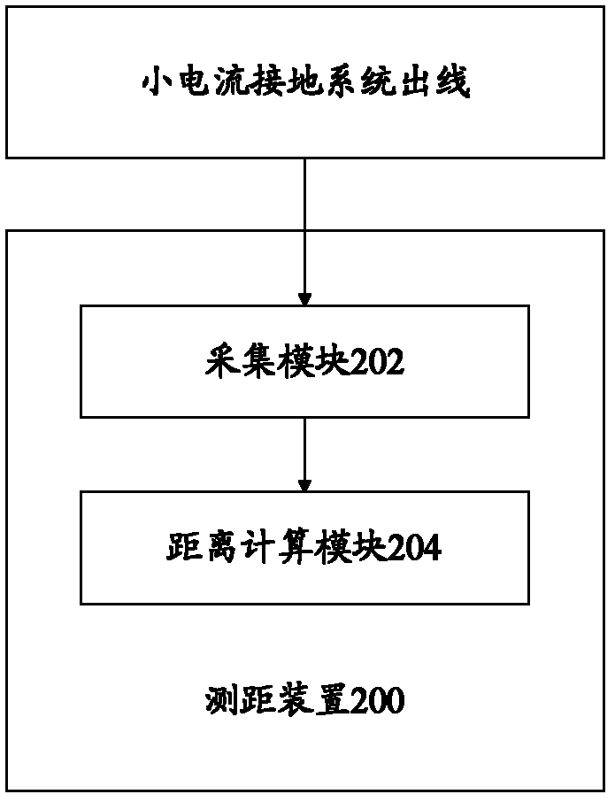
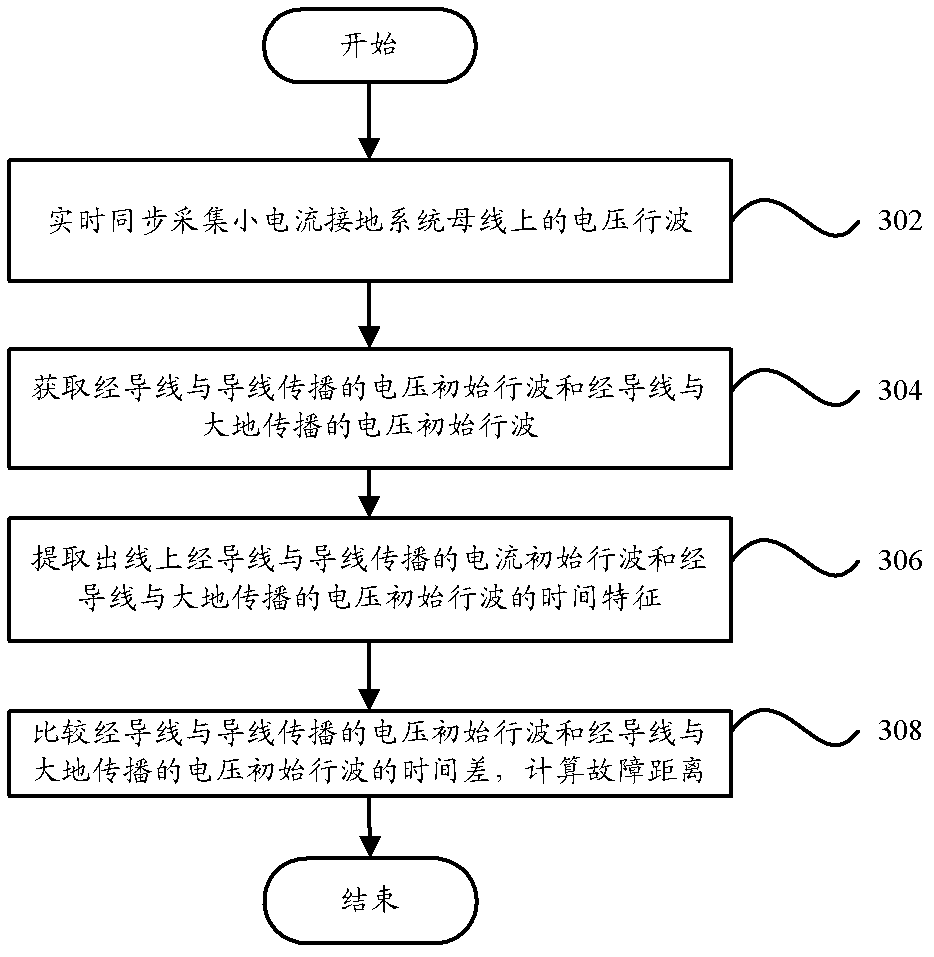

Image

  • Distance measuring method and distance measuring device for single-phase grounding of low-current grounding system
  • Distance measuring method and distance measuring device for single-phase grounding of low-current grounding system
  • Distance measuring method and distance measuring device for single-phase grounding of low-current grounding system

Examples


Embodiment Construction

[0016] In order to understand the above-mentioned purpose, features and advantages of the present invention more clearly, the present invention will be further described in detail below in conjunction with the accompanying drawings and specific embodiments.

[0017] In the following description, many specific details are set forth in order to fully understand the present invention, but the present invention can also be implemented in other ways different from those described here, therefore, the present invention is not limited to the specific embodiments disclosed below limit.

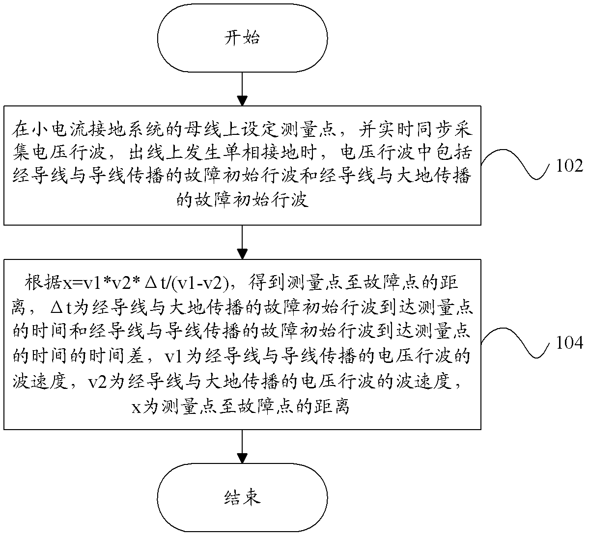
[0018] figure 1 is a flowchart of the ranging method according to the present invention.

[0019] Such as figure 1 As shown, the present invention provides a distance measuring method for measuring the position of the single-phase ground fault point of the small current grounding system, including: step 102, setting the measurement point on the busbar of the small current grounding system, and synch...


PUM


Abstract

The invention discloses a distance measuring method, which is used for measuring the position of a fault point of a low-current grounding system, wherein the fault point generates single-phase grounding. The distance measuring method comprises the following steps of: step 102, setting a measuring point on a bus of the low-current grounding system, and synchronously collecting a voltage traveling wave in time, wherein when the single-phase grounding is generated on an outgoing line, the traveling wave comprises a fault initial traveling wave propagated with a conducting wire through the conducting wire and a fault initial traveling wave propagated with the earth through the conducting wire; and step 104, obtaining a distance from the measuring point to the fault point according to x=v1*v2*[delta]t / (v1-v2), wherein [delta]t is the time difference of the time that the fault initial traveling wave propagated with the earth through the conducting wire reaches to the measuring point and the time that the fault initial traveling wave propagated with the conducting wire through the conducting wire reaches to the measuring point, v1 is the wave speed of the traveling wave propagated with the conducting wire through the conducting wire, v2 is the wave speed of the traveling wave propagated with the earth through the conducting wire, and x is the distance from the measuring point to the fault point. The invention further discloses a distance measuring device. According to the distance measuring method and the distance measuring device, the position of the fault point generating the single-phase grounding can be effectively detected.

Description

technical field [0001] The invention relates to the field of electric power system relay protection, in particular to a distance measuring method and a distance measuring device for measuring the position of a single-phase ground fault point in a small current grounding system. Background technique [0002] The small current grounding system refers to the system with a small fault current when a single-phase grounding fault occurs, specifically refers to the neutral point not grounded, the neutral point through the arc suppression coil or the neutral point through the high resistance grounding system, commonly known as the small current system. When a single-phase ground fault occurs in a small current system, since it does not constitute a short-circuit circuit, it is not necessary to quickly cut off the faulty line and stop the user's power supply. According to statistics, single-phase ground faults account for more than 70% of all faults in the entire power distribution s...

Claims


Application Information

Patent Timeline
Patent Type & Authority Applications(China)
IPC IPC(8): G01R31/08
Inventor 施慎行董新洲齐天来
Owner TSINGHUA UNIV
Learn More