
Movable contact for switching

A technology of moving contacts and switches, applied in the field of improvement of movable contacts, can solve the problems of frequent failure of recovery, inability to return to the original state, and poor recovery, and achieve the effect of avoiding poor recovery.

Inactive Publication Date: 2012-07-04
FUJI ELECTRONIC IND JP
View PDF5 Cites 0 Cited by
  • Summary
  • Abstract
  • Description
  • Claims
  • Application Information

AI Technical Summary

Problems solved by technology

For such a conventional movable contact, if a high load is applied to the central cylindrical protrusion, for example, a static load of 10 kg for 1 minute, a static load of 20 kg for 5 seconds, or a static load of 40 kg for 1 second, the cylindrical protrusion will be flattened. , The dome-shaped movable contact is deformed in the direction of diameter expansion in a manner that protrudes outward as a whole, and the phenomenon that it cannot return to the original shape occurs, that is, poor recovery
[0003] In particular, when the periphery of the cylindrical protrusion is formed by a curved surface with a small gradient and a small protruding contact that contacts the fixed contact is formed on the periphery of the cylindrical protrusion, the movable contact deforms in the direction of diameter expansion under a high load. When using a small protruding contact point as a fulcrum, a large deformation occurs beyond the reverse recovery limit, so it is easy to cause multiple recovery failures

Method used


Image

  • Movable contact for switching
  • Movable contact for switching
  • Movable contact for switching

Examples


Embodiment Construction

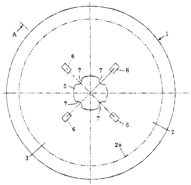
[0029] exist figure 1 as well as figure 2 Among them, the movable contact 1 for a switch according to the present invention is configured as a contact piece 2 that can be reversed by bending a substantially circular conductive spring material into a dome shape. The conductive spring material is a round silver-plated or nickel-plated stainless steel plate with a thickness of about 0.04-0.1 mm, and if it is an operation key of a mobile phone, its size is about 3-6 mm in diameter. In addition, the contact piece 2 is not limited to a circular conductive spring material, and can also be made of an appropriate shape according to the assembly object, such as an oval, oval, rhombus, and rectangular conductive spring material, and a diamond-shaped, rectangular conductive spring material. The corner part is made of conductive spring material in the shape of a circular arc or a straight line.

[0030] The contact piece 2 has a dome-shaped, for example, truncated conical bulging portio...


PUM


Abstract

The invention provides a movable contact for switching (1) which prevents a dome-shaped movable contact for switching from being deformed beyond necessity, and also prevents a contactor from being poorly recovered in advance. The movable contact for switching comprises a reversely recoverable contactor (2) formed by curving an electrically conductive leaf material into a dome-like shape while forming a rigid addition bulge (5) at the center of a convex surface (3) of the contactor, the bulge protruding toward a dome-shaped convex side, a plurality of contact points (6) formed by forming smallprojections concentrically positioned around the bulge (5), on a concave surface (6) of the contactor (2), the small projections protruding toward a dome-shaped concave side, and a recess (7) for usein prevention of deformation, on a convex side face of the bulge (5), formed by depressing a part of the circumference of the bulge (5), on a straight line connecting the center of the bulge (5) witheach of the contact points (6), toward the center.

Description

technical field [0001] The present invention relates to a switch incorporated in a signal input portion of various devices, and more particularly to an improvement of a dome-shaped movable contact with a knocking function for a switch. Background technique [0002] Patent Document 1 discloses such a dome-shaped movable contact. The movable contact forms a cylindrical protrusion at the center of a dome-shaped contact piece. For such a conventional movable contact, if a high load is applied to the central cylindrical protrusion, for example, a static load of 10 kg for 1 minute, a static load of 20 kg for 5 seconds, or a static load of 40 kg for 1 second, the cylindrical protrusion will be flattened. , The entire dome-shaped movable contact is deformed in the direction of diameter expansion in such a way that it protrudes outward, and there is a phenomenon that it cannot return to its original shape, that is, poor recovery. [0003] In particular, when the periphery of the cy...

Claims


Application Information

Patent Timeline
IPC IPC(8): H01H13/48
CPCH01H13/705H01H2215/022H01H2221/05
Inventor 增田政次
Owner FUJI ELECTRONIC IND JP
Learn More