Faraday shield and plasma processing equipment

A Faraday shielding and molecular technology, applied in discharge tubes, electrical components, circuits, etc., can solve the problems of reducing the production efficiency of plasma processing equipment, polluting the annular dielectric window, increasing the labor intensity of workers, etc., to reduce the time to interrupt the process, The effect of increasing complexity and reducing labor intensity

Active Publication Date: 2012-07-04
BEIJING NAURA MICROELECTRONICS EQUIP CO LTD
View PDF6 Cites 11 Cited by
  • Summary
  • Abstract
  • Description
  • Claims
  • Application Information

AI Technical Summary

Problems solved by technology

[0005] Although the first Faraday shielding unit 71 and the second Faraday shielding unit 72 are staggered to prevent most of the plasma from passing through the Faraday shield, there are still some plasmas that can pass through the Faraday shield through the slit and pollute the annular dielectric window 6
Therefore, in the actual use process, the ring-shaped dielectric window 6 needs to be cleaned frequently, which not only increases the labor intensity of the workers, but also causes process interruption and reduces the production efficiency of the plasma processing equipment.

Method used


Image

  • Faraday shield and plasma processing equipment
  • Faraday shield and plasma processing equipment
  • Faraday shield and plasma processing equipment

Examples


Embodiment Construction

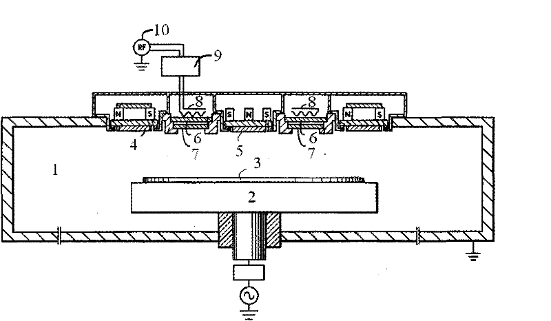
[0023] In order to enable those skilled in the art to better understand the technical solutions of the present invention, the Faraday shield and plasma processing equipment provided by the present invention will be described in detail below with reference to the accompanying drawings.

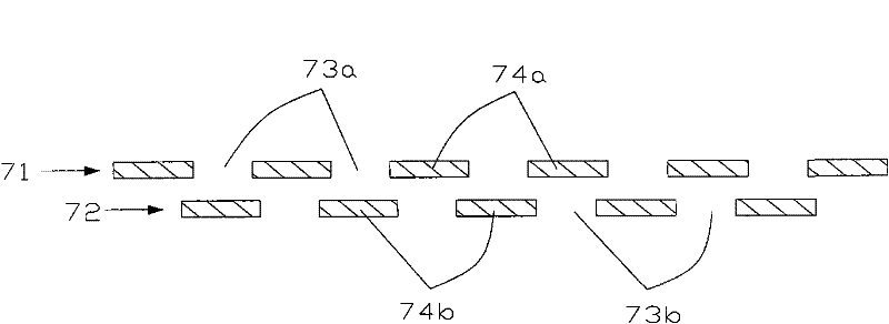
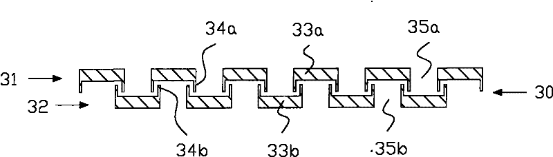
[0024] image 3 A cross-sectional view of a Faraday shield provided by an embodiment of the present invention, Figure 4 Partial enlarged view of the Faraday shield provided for the present invention. Please also refer to image 3 and Figure 4 In this embodiment, the Faraday shielding is a double-layer structure, including a first Faraday shielding unit 31 and a second Faraday shielding unit 32 arranged side by side, and the first Faraday shielding unit 31 and the second Faraday shielding unit 32 are separated by a certain distance to form a gap 30. Both the first Faraday shielding unit 31 and the second Faraday shielding unit 32 include a plurality of shielding segments arranged at interv...


PUM


Abstract

The invention provides a Faraday shield and plasma processing equipment. The Faraday shield comprises at least two shield units which are arranged side by side, wherein each shield unit comprises a plurality of shield sections which are arranged at intervals, and the shield sections in the two adjacent shield units are arranged in a staggered mode; and the shield sections are provided with blocking parts of which the orientations are opposite and which are arranged in a staggered mode, and a shield channel is formed between the blocking parts of the two shield sections which are arranged in a staggered mode. According to the Faraday shield, plasma can be reduced and even prevented from passing through the Faraday shield by the blocking parts on the shield sections.

Description

technical field [0001] The invention belongs to the field of plasma processing equipment, and relates to a Faraday shield and plasma processing equipment containing the Faraday shield. Background technique [0002] Magnetron sputtering technology is to introduce the surface of the target into a magnetic field, and use the interaction between the magnetic field and the electrons to make the electrons run in a spiral shape near the surface of the target to impact the ionization of gas molecules to generate ions, and the generated ions hit the target under the action of the electric field The target material is sputtered from the surface of the material. At the same time, the magnetic field can confine the charged particles and increase the density of the plasma, which can increase the sputtering rate. Therefore, magnetron sputtering technology is widely used in thin film deposition and etching processes. [0003] figure 1 It is a schematic structural diagram of a plasma pro...

Claims


Application Information

Patent Timeline
Patent Type & Authority Applications(China)
IPC IPC(8): H01J37/09H01J37/32
Inventor 王一帆武晔吕铀
Owner BEIJING NAURA MICROELECTRONICS EQUIP CO LTD
Why Eureka
Try Eureka