
Uniform linear array calibration method based on strong scattering points

A technology of uniform linear array and calibration method, which is applied in the direction of antenna array, antenna, electrical components, etc., can solve the problem that the array calibration method is not accurate enough, and achieve the effect of accurate calibration

Inactive Publication Date: 2012-07-04
HARBIN INST OF TECH
View PDF5 Cites 15 Cited by
  • Summary
  • Abstract
  • Description
  • Claims
  • Application Information

AI Technical Summary

Problems solved by technology

[0004] The purpose of the present invention is to provide a uniform linear array calibration method based on strong scatterers in order to solve the problem that the existing array calibration method is not accurate enough

Method used


Image

  • Uniform linear array calibration method based on strong scattering points
  • Uniform linear array calibration method based on strong scattering points
  • Uniform linear array calibration method based on strong scattering points

Examples


specific Embodiment approach 1

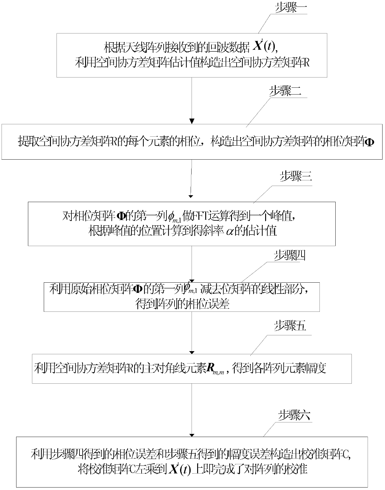
[0023] Specific implementation mode one: combine figure 1 Describe this embodiment mode, a kind of uniform linear array calibration method based on strong scatterer of the present invention, it comprises the following steps:

[0024] Step 1: According to the echo data X′(t)=ГX(t)+n(t) received by the antenna array, use the estimated value of the spatial covariance matrix Construct the spatial covariance matrix R;

[0025] Where X(t) is the M×1-dimensional snapshot data vector of the array, n(t) is the M×1-dimensional noise vector of the array, Г is the array phase error matrix, and the specific expression is where set {g m : m=1, 2, ..., M} represents the gain on each array element, Represents the array phase inconsistency error, j represents an imaginary number; where N is the number of snapshots;

[0026] Step 2: Extract the phase of each element of the spatial covariance matrix R, and construct the phase matrix Φ of the spatial covariance matrix; R m,k is the mth ro...

specific Embodiment approach 2

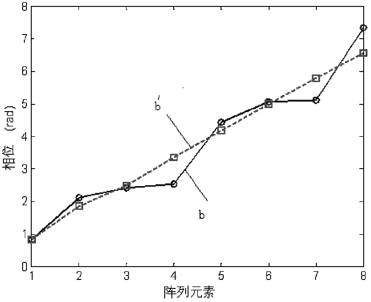
[0031] Specific implementation mode two: combination image 3 Describe this embodiment. The difference between this embodiment and the first embodiment is that in step 3, the first column φ of the phase matrix Φ m,1 In the process of doing FFT operation, a binomial fitting method is adopted:

[0032] Step 1: For the first column φ of the phase matrix Φ m,1 Perform FFT to get the abscissa corresponding to the maximum value as F, and the magnitude corresponding to F is y(F), then take (F-1, y(F-1)), (F+1, y(F+1 )) coordinates of two points;

[0033] Step 2: Use the three points obtained above to pair the binomial y(f)=k 0 +k 1 f+k 2 f 2 Fit to find the binomial coefficient k 0 , k 1 , k 2, thus taking the derivative of y(f) to obtain the frequency corresponding to the maximum point, which is the slope to be estimated

[0034] In order to reduce the influence of FFT's fence effect, a binomial fitting method is used to improve the accuracy of slope estimation; when cal...


PUM


Abstract

The invention relates to a uniform linear array calibration method based on strong scattering points, and aims to solve the problem that a conventional array calibration method is not accurate enough. The uniform linear array calibration method comprises the following steps: a spatial covariance matrix R is constructed by utilizing a spatial covariance matrix estimated value according to echo data received by an antenna array; phase positions of all elements of the spatial covariance matrix R are extracted to construct a phase matrix Phi of the spatial covariance matrix; the first row Phi m,1 of the phase matrix Phi is subject to FFT (Fast Fourier Transform) operation to obtain a peak value, the estimated value of slope Alpha is obtained according to the position of the peak value, and the linear part of the phase matrix is subtracted from the first row Phi m,1 of the original phase matrix Phi according to the estimated value of the slope Alpha to obtain the phase error of the array; a calibrated matrix C is constructed by utilizing the obtained phase error and amplitude error according to all the obtained array element amplitudes; and array calibration is completed through pre-multiplying the calibrated matrix C to the received echo data. The uniform linear array calibration method is used for calibrating uniform arrays and is more accurate in calibration.

Description

technical field [0001] The invention relates to a uniform linear array calibration method based on strong scattering points. Background technique [0002] An array antenna is an antenna system composed of many identical individual antennas arranged according to certain rules, also known as an antenna array. Array antennas can be divided into linear arrays and area arrays according to the unit arrangement. The most commonly used linear array is a linear array in which the centers of each unit are arranged in a straight line at equal intervals, also called a uniform linear array. The units of the line array are also arranged at unequal distances, and the centers of the units may not be arranged on a straight line, for example, arranged on a circle. A plurality of linear arrays are arranged at a certain interval on a certain plane to form a planar array, and if the centers of each unit are arranged on a spherical surface, a spherical array is formed. [0003] In practical ap...

Claims


Application Information

Patent Timeline
IPC IPC(8): H01Q21/00
Inventor 位寅生许荣庆宋孝果童鹏
Owner HARBIN INST OF TECH
Learn More