Adjustable axial piston machine having a bearing shell for the pivot cradle

A technology of axial plunger machine and bearing bush, which is applied in the field of axial plunger machine, can solve problems such as machine failure and bearing bush failure, and achieve the effects of restraining fracture, safe and reliable support, and improving service life

Active Publication Date: 2014-12-24
ROBERT BOSCH GMBH
View PDF6 Cites 0 Cited by
  • Summary
  • Abstract
  • Description
  • Claims
  • Application Information

AI Technical Summary

Problems solved by technology

[0004] These bending moments lead to enormous loads and also to failure of the bearing shells and thus of the machine

Method used


Image

  • Adjustable axial piston machine having a bearing shell for the pivot cradle
  • Adjustable axial piston machine having a bearing shell for the pivot cradle
  • Adjustable axial piston machine having a bearing shell for the pivot cradle

Examples


Embodiment Construction

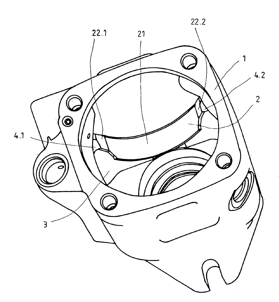
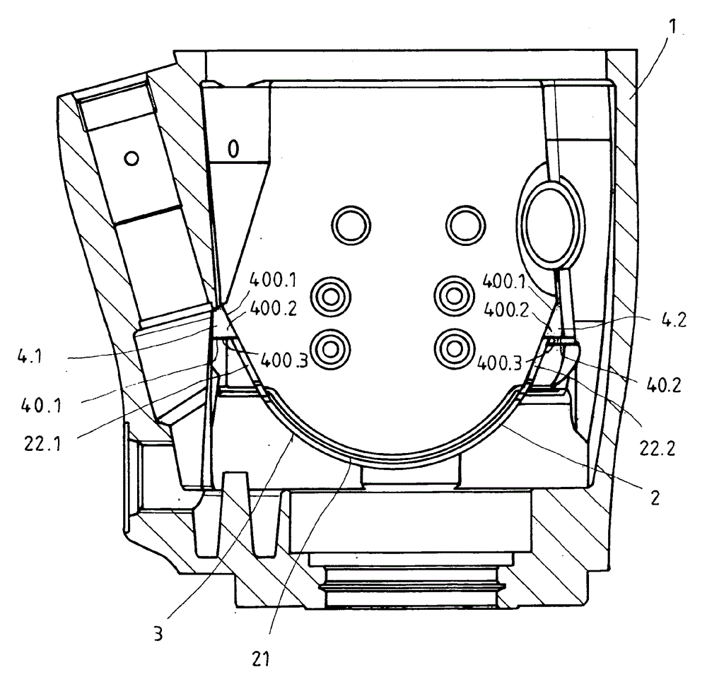
[0025] figure 1 A perspective view of the housing 1 of the adjustable axial piston machine according to the invention is shown. In the housing 1 , a bearing shell 2 is arranged in an interior space 3 . For reasons of clarity, the cradle is not shown. However, the cradle is supported on the housing 1 via the bearing shell 2 in a known manner. The bearing shell 2 has for this purpose an annular segment-shaped bearing segment 21, a straight first bearing shell end region 22. l extending in one plane and a straight second bearing shell end also extending in one plane Area 22.2. The first bearing shell end region 22.1 bears in the event of circumferential forces occurring in the bearing section 21 on first positioning lugs 4.1, which in turn are formed on the housing. The second bearing shell end region 22.2 bears in the event of circumferential forces occurring in the bearing section 21 on a second positioning lug 4.2, which is likewise formed on the housing. The illustrated ...


PUM


Abstract

An adjustable axial piston machine includes a housing, a pivot cradle and a bearing shell which is arranged between the housing and the pivot cradle. The bearing shell includes a bearing section in the shape of an annular section with an inner end and a bearing shell end region which extends in one plane with an outer end. A bearing surface, the geometry of which corresponds to the bearing section, is provided on the housing. An outer supporting force point at the outer end and an inner supporting force point at the inner end lie on a straight line which extends on the inner supporting force point tangentially with respect to the bearing section. If a force is present in the circumferential direction of the bearing section, the inner supporting force point and the outer supporting force point are subjected to a supporting force substantially parallel to the straight line.

Description

technical field [0001] The invention relates to an adjustable axial piston machine according to claim 1 . Background technique [0002] US 6,676,294 B2 shows several rotary cradles for an adjustable axial piston machine by means of a bearing shell arranged in a housing with a main section in the form of an annular section and at least one support area. A system supported in the housing. Here, a bearing shell is shown, from which projections with a radial component protrude from the outer surface of the ring-segment-shaped main section for supporting circumferential forces. [0003] If a force acts on the bearing shell in the circumferential direction, the radial component leads to a bending moment due to the resulting lever. [0004] These bending moments lead to enormous loads and also to failure of the bearing shells and thus of the machine. Contents of the invention [0005] It is therefore the object of the present invention to provide an adjustable axial piston mac...

Claims


Application Information

Patent Timeline
Patent Type & Authority Patents(China)
IPC IPC(8): F04B1/20F16C19/50F16C33/08F16C33/58
CPCF16C33/08F04B1/2064F01B3/0064F16C33/58F16C2360/42F16C2226/74F01B3/0073F04B1/2085F16C19/502F16C2360/00
Inventor R.贝尔泽
Owner ROBERT BOSCH GMBH
Why Eureka
Try Eureka