Optical distance measuring device

A technology for measuring devices and optical distances, which is applied in active optical measuring devices, measuring devices, line-of-sight measurement, etc., can solve problems such as incompatibility with CMOS technology, and achieve the effect of improving dynamic range and reducing complexity

Active Publication Date: 2012-07-04
ROBERT BOSCH GMBH
View PDF6 Cites 62 Cited by
  • Summary
  • Abstract
  • Description
  • Claims
  • Application Information

AI Technical Summary

Problems solved by technology

[0008] Since the described conventional distance measuring devices use photosensitive elements, such as PIN diodes or APDs (avalanche photodiodes), which provide analog measurement signals with a large bandwidth, it may be necessary to use complex analysis electronics to analyze these analog measurement signals
These photosensitive elements, which work in analog mode, are usually not compatible with other CMOS technologies used in measurement equipment

Method used


Image

  • Optical distance measuring device
  • Optical distance measuring device
  • Optical distance measuring device

Examples


Embodiment Construction

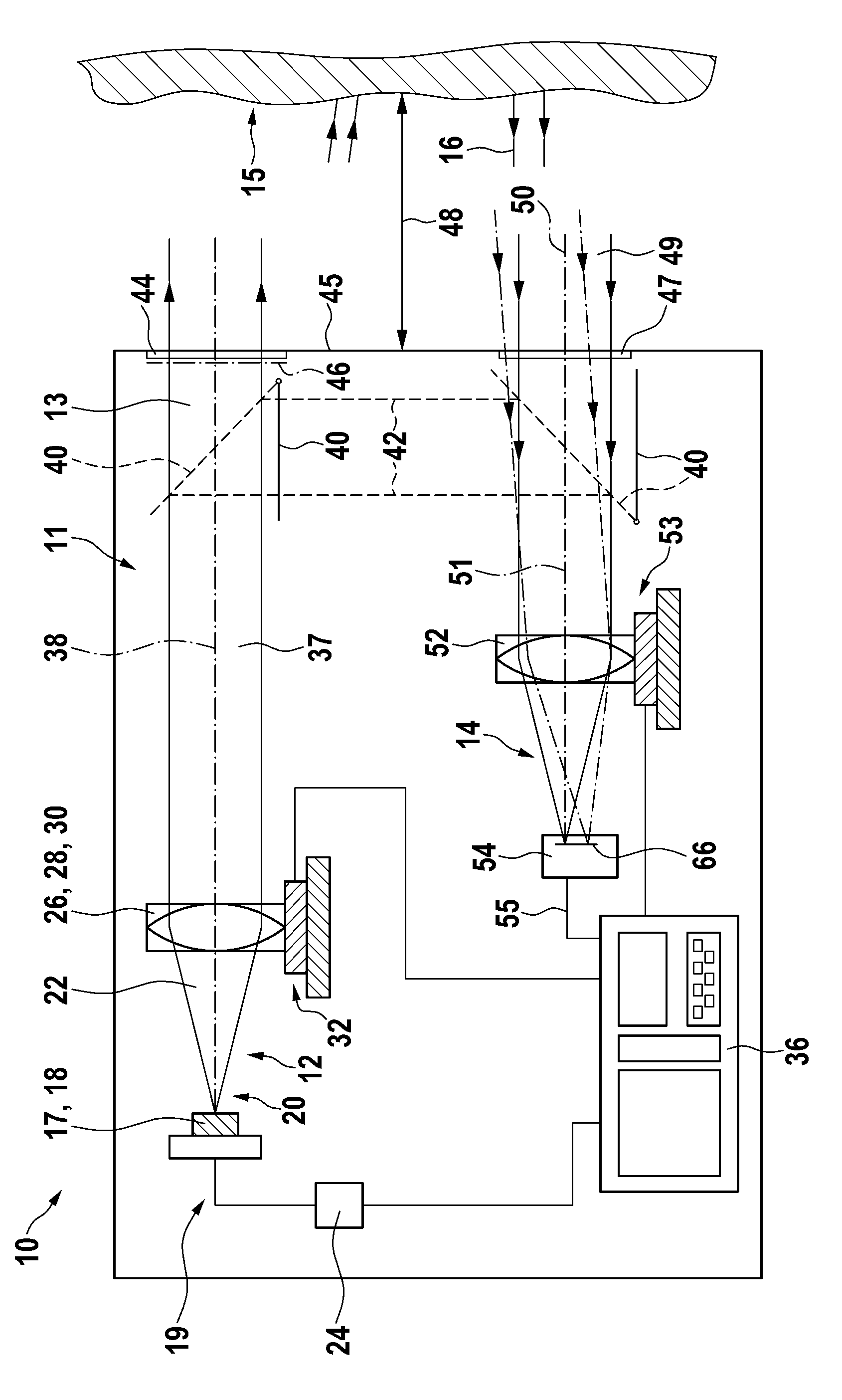
[0043] exist figure 1 The measuring device 10 for optical distance measurement according to the invention is shown schematically with the most important components for describing its function.

[0044] Measuring device 10 has a housing 11 in which a transmitting device 12 for transmitting optical measuring radiation 13 and a receiving device 14 for detecting measuring radiation 16 returning from a target object 15 are arranged.

[0045] The emission device 12 contains a light source, which is realized in the exemplary embodiment shown by a semiconductor laser diode 18 . Laser diode 18 emits laser beam 20 in the form of beam 22 visible to the human eye. The laser diode 18 is operated for this purpose by a control device 24 which generates a temporal modulation of the electrical input signal 19 of the laser diode 18 via corresponding electronics. This modulation of the diode current can achieve that the optical measuring radiation 13 for distance measurement is likewise tempor...


PUM


Abstract

The invention relates to a measuring device (10) for optically measuring a distance to a target object (15). Said measuring device (10) comprising an emitter device (12) for emitting an optical measuring beam (13) to the target object (15), a capturing device (14) comprising a detection surface (66) for detecting an optical beam (16) returned by the target object (15) and an evaluation device (36). Said detection surface (66) has a plurality of pixels, each pixel having at least one SPAD (single photon avalanche diode) and each of the plurality of pixels is connected to the evaluation device (36). Said emitting device and the capturing device are configured in such a manner that the optical measurement beam returned by the target object simultaneously illuminates a plurality of pixels. Said evaluation device is configured in order to determine the distance between the measuring device and the target object based on the evaluation of detection signals of several pixels. Advantageously, at least some of the pixels comprise respectively a plurality of SPADs, the number or surface of SPAD's contained in a pixel can vary depending on the place of the pixel within the detection surface.

Description

technical field [0001] The invention relates to a measuring device for measuring a distance between a measuring device and a target object by means of optical measuring radiation. Background technique [0002] Optical distance measuring devices are known which direct a time-modulated beam of light at a target object whose distance from the measuring device is to be determined. The return light reflected or scattered by the direction-finding target object is at least partially detected by the device and used to determine the distance to be measured. Typical measuring ranges here lie in the distance range of a few centimeters up to several hundred meters. [0003] In order to be able to use the light beam to measure the distance to the target object, the light beam is temporally modulated, for example, in terms of its intensity. For example, a light pulse can be transmitted and the propagation time of the light pulse from transmission until detection can be measured and the ...

Claims


Application Information

Patent Timeline
Patent Type & Authority Applications(China)
IPC IPC(8): G01C15/00G01C3/08G01S17/08H01L31/107G01S17/10G01S7/4861G01S7/491G01S7/4913G01S17/89
CPCG01S17/08G01C3/08G01S17/89G01S7/4816G01C15/002G01S7/4861G01S17/10G01S7/491G01S7/4913
Inventor A.埃塞勒O.沃斯特B.施米德科
Owner ROBERT BOSCH GMBH
Why Eureka
Try Eureka