Illumination optical unit for microlithography

An optical unit and microlithography technology, applied in microlithography exposure equipment, optical elements, optics, etc., can solve the problem of reducing the total transmission rate of the illumination optical unit, and achieve the effect of high manufacturing cost efficiency

Inactive Publication Date: 2012-07-04
CARL ZEISS SMT GMBH
View PDF11 Cites 4 Cited by
  • Summary
  • Abstract
  • Description
  • Claims
  • Application Information

AI Technical Summary

Problems solved by technology

For this purpose, additional polarizing elements have hitherto been used in the illumination optics, but said elements also absorb part of the radiation and thus reduce the overall transmission of the illumination optics

Method used


Image

  • Illumination optical unit for microlithography
  • Illumination optical unit for microlithography
  • Illumination optical unit for microlithography

Examples


Embodiment Construction

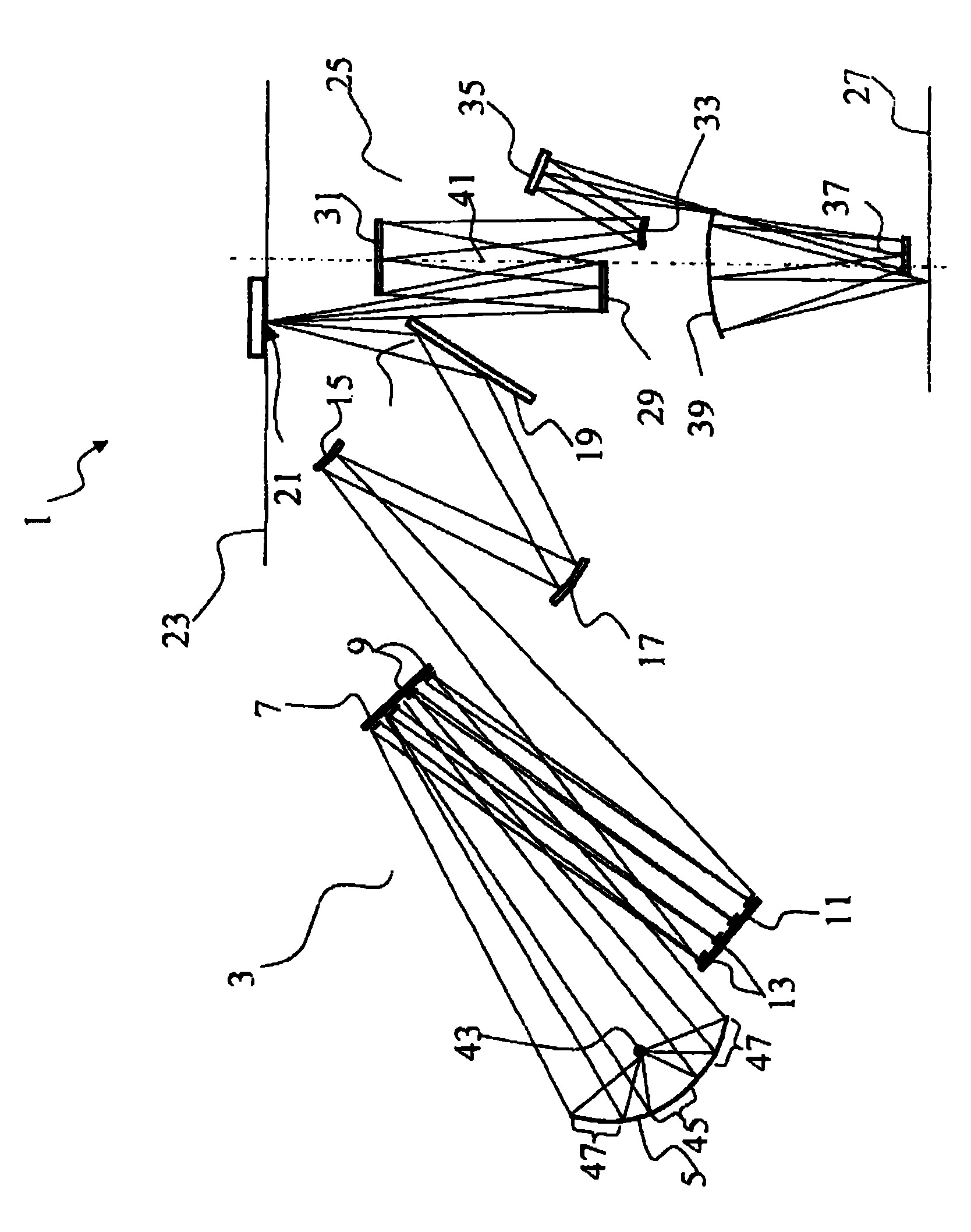
[0037] The reference designation is selected so that it is provided with one or two digitsfigure 1 objects shown in . Objects shown in other figures have reference numbers of three or more digits, with the last two digits representing the object and the preceding digits representing the number of the figure showing the object. Therefore, the last two digits of the reference numerals of the same objects shown in multiple figures are the same.

[0038] figure 1 The construction of a projection exposure system 1 according to the invention is shown, which comprises an illumination optics unit 3 . In this case, the illumination optical unit 3 comprises a mirror concentrator 5 , a first reflective optical element 7 with a first facet element 9 and a second reflective optical element 11 with a plurality of second facet elements 13 . A first telescopic mirror 15 and a second telescopic mirror 17 are arranged in the optical path downstream of the second reflective optical element 11,...


PUM


Abstract

Illumination optical unit comprising a collector mirror, which produces a polarization distribution that is applied to the first faceted optical element during the operation of the illumination optical unit, wherein there are at least two first facet elements to which radiation having a differing polarization is applied, and furthermore the first faceted optical element has at least one first state in which the normal vectors of the reflective surfaces of the first facet elements are selected in such a way that a first predetermined polarization distribution results at the location of the object field during the operation of the illumination optical unit.

Description

technical field [0001] The invention relates to an illumination optics unit for EUV microlithography, the illumination optics unit comprising a mirror concentrator and comprising a first facet optical element having a plurality of first facet elements, the illumination optics The cells are used to illuminate an object field in an object plane, wherein each first facet element has a reflective surface, the direction of its normal vector determining the spatial orientation of the reflective surface. The invention also relates to a projection exposure apparatus comprising an illumination optical unit of this type. Background technique [0002] Projection exposure systems of this type are known from US 6,859,328 and from WO 2006 / 111319 A2. [0003] In microlithography, it is also known that it is desirable to illuminate the structure to be imaged with a predetermined polarization distribution, thus increasing the contrast during downstream imaging. For this purpose, additional...

Claims


Application Information

Patent Timeline
Patent Type & Authority Applications(China)
IPC IPC(8): G02B5/30G21K1/00G03F7/20
CPCG21K1/16G03F7/70116G02B27/0977G03F7/70175G03F7/70233G02B27/0905G21K1/06G21K2201/06G21K2201/064G03F7/70075G03F7/702G03F7/70566G21K2201/067G02B5/30G02B27/18G03F7/20
Inventor D.菲奥尔卡R.施图茨尔
Owner CARL ZEISS SMT GMBH
Why Eureka
Try Eureka