Stepping switch comprising vacuum switching tubes

A technology of vacuum switching tubes and tap changers, which is applied in the direction of electric switches, instruments, and adjustment of electric variables, etc. It can solve the problem that the structural space of the load transfer switch is no longer sufficient, and achieve the effect of a compact structure.

Active Publication Date: 2012-07-04
MASCHFAB REINHAUSEN GEBR SCHEUBECK GMBH & CO KG
View PDF7 Cites 7 Cited by
  • Summary
  • Abstract
  • Description
  • Claims
  • Application Information

AI Technical Summary

Problems solved by technology

In this case, often with this known solution, the installation space provided in the load changeover switch is no longer sufficient, and structurally unfavorable compromise solutions have to be accepted.

Method used


Image

  • Stepping switch comprising vacuum switching tubes
  • Stepping switch comprising vacuum switching tubes
  • Stepping switch comprising vacuum switching tubes

Examples


Embodiment Construction

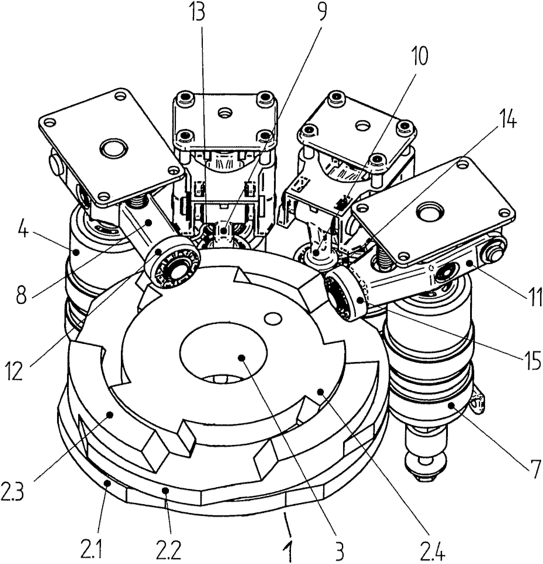
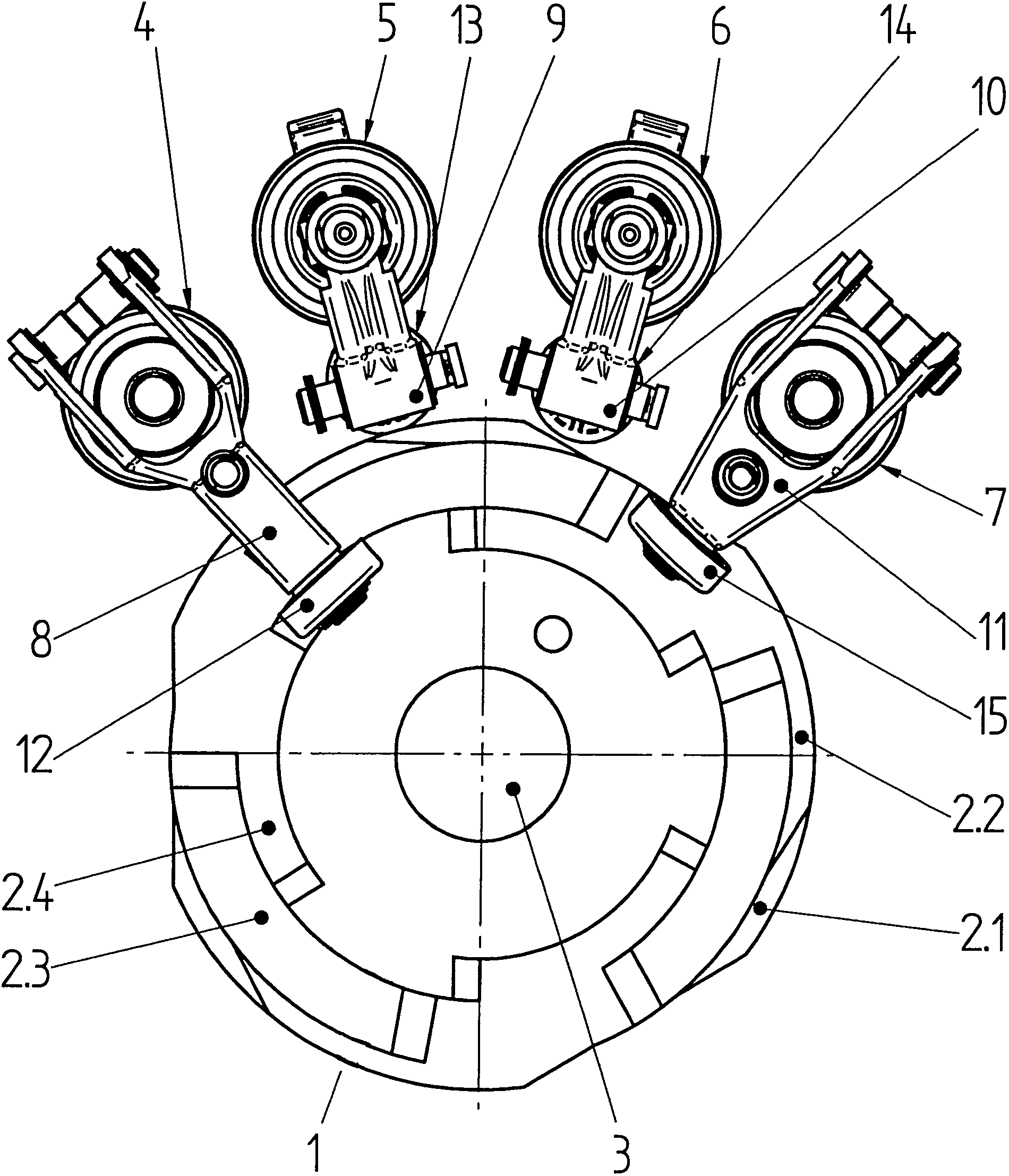
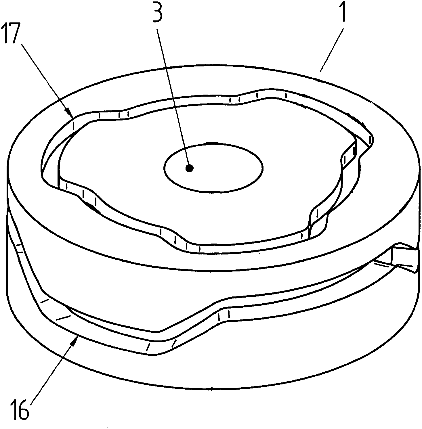
[0015] For clarity, the following is in figure 1 Only the important inventive parts of the tap changer including the vacuum interrupter according to the invention are shown and described in the text. Description and illustration of features known per se and components not essential to the essence of the invention are omitted. therefore, figure 1 An embodiment of a cam disc 1 is shown, which comprises a plurality of control cams 2.1, 2.2, 2.3 and 2.4, which in cooperation with them control the temporal switching process of the contact system for the changeover tap changer and Suitable for handling multiple vacuum interrupters. Two control cams 2 . The rods 9 and 10 are connected to the vacuum switching tubes, which are not visible in this view, said rollers engaging the profiled contours of the respective control cams 2.1 and 2.2. Since the rollers 13 and 14 are used here for engaging surface topography other than circular contours, they can also be replaced by other equall...


PUM


Abstract

The invention relates to a stepping switch comprising vacuum switching tubes. The general inventive concept consists in providing one or more cam disks which have profiled circumferential contours both on the upper or lower face as well as on the lateral face, said contours being in the shape of cams for example, so that the vacuum switching tubes can be actuated by both the profiled circumferential contour of the lateral face as well as by the contour of the upper or lower face.

Description

technical field [0001] The invention relates to a tap changer comprising a vacuum interrupter according to the preamble of claim 1 . Background technique [0002] Tap changers have been used worldwide for many years for the continuous switching between different winding taps of tapped transformers. Such a tap changer usually includes: a selector for powerlessly selecting the corresponding winding tap to be switched to of the adjustable transformer; and a load changeover switch for actually switching from the switched winding tap to the new Preselected winding taps. Jump switching is usually achieved by means of an energy store, which rotates a switching shaft rapidly when the energy store is actuated. A load changeover switch usually also has switching contacts and resistive contacts. The switching contacts are used here for the direct connection of the respective winding tap to the load branch, and the resistor contacts are used for momentary switching, ie bonding, by me...

Claims


Application Information

Patent Timeline
Patent Type & Authority Applications(China)
IPC IPC(8): H01H9/00
CPCH01H9/0027H01H9/0038G05F1/10
Inventor S・弗雷德
Owner MASCHFAB REINHAUSEN GEBR SCHEUBECK GMBH & CO KG
Why Eureka
Try Eureka