Eureka AIR delivers breakthrough ideas for toughest innovation challenges, trusted by R&D personnel around the world.

Mandibular condyle fracture reduction dilator

A mandible and distractor technology, applied in the field of medical devices, can solve the problems of increasing maxillofacial trauma and scars, uncontrollable degree of condylar descending, facial nerve damage, etc., so as to increase tissue damage, scars, subcondylar The degree of displacement is easy to control, and the effect of opening the mandible is convenient

Inactive Publication Date: 2012-07-11
周剑虹
View PDF7 Cites 7 Cited by
  • Summary
  • Abstract
  • Description
  • Claims
  • Application Information

AI Technical Summary

Problems solved by technology

[0005] The present invention provides a mandibular condylar fracture reduction spreader, the main purpose of which is to overcome the difficulty of fracture exposure in the existing mandibular condylar fracture reduction operation, the degree of condyle downward movement is difficult to control, increase maxillofacial trauma and scars, and increase facial nerve possible damage

Method used


Image

  • Mandibular condyle fracture reduction dilator
  • Mandibular condyle fracture reduction dilator
  • Mandibular condyle fracture reduction dilator

Examples


Embodiment Construction

[0024] Refer to the attached figure 1 to attach Image 6 Specific embodiments of the present invention will be described.

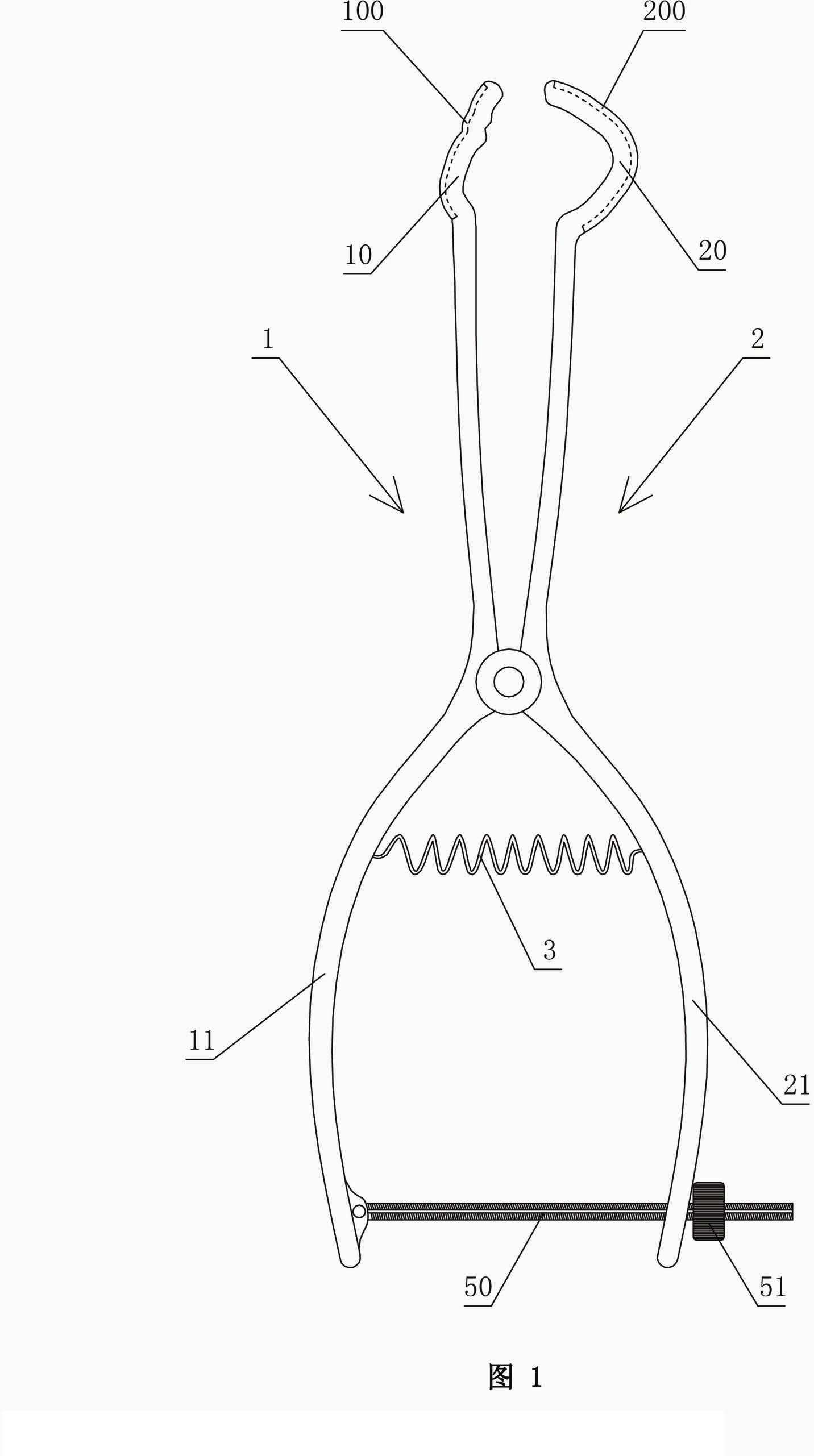
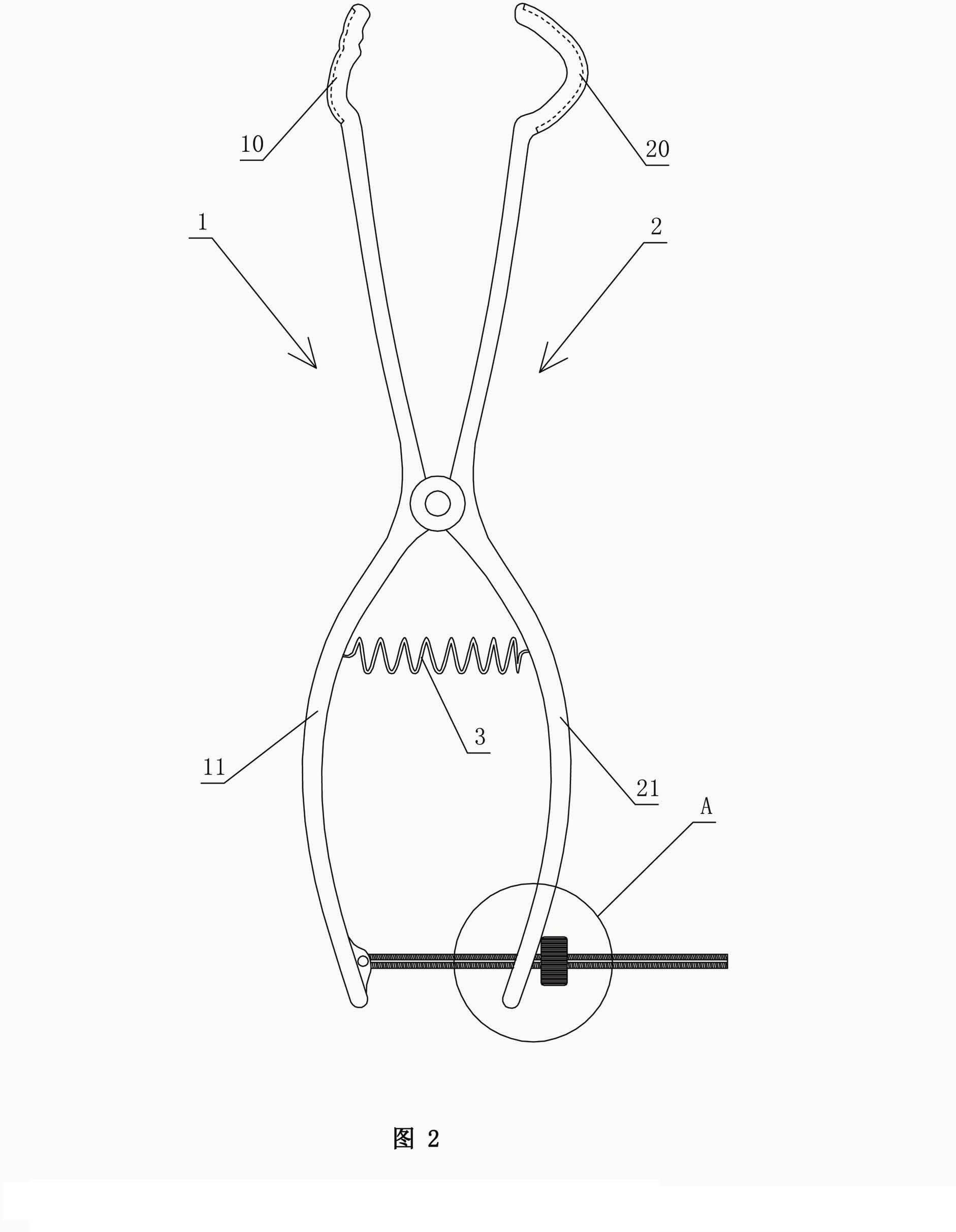
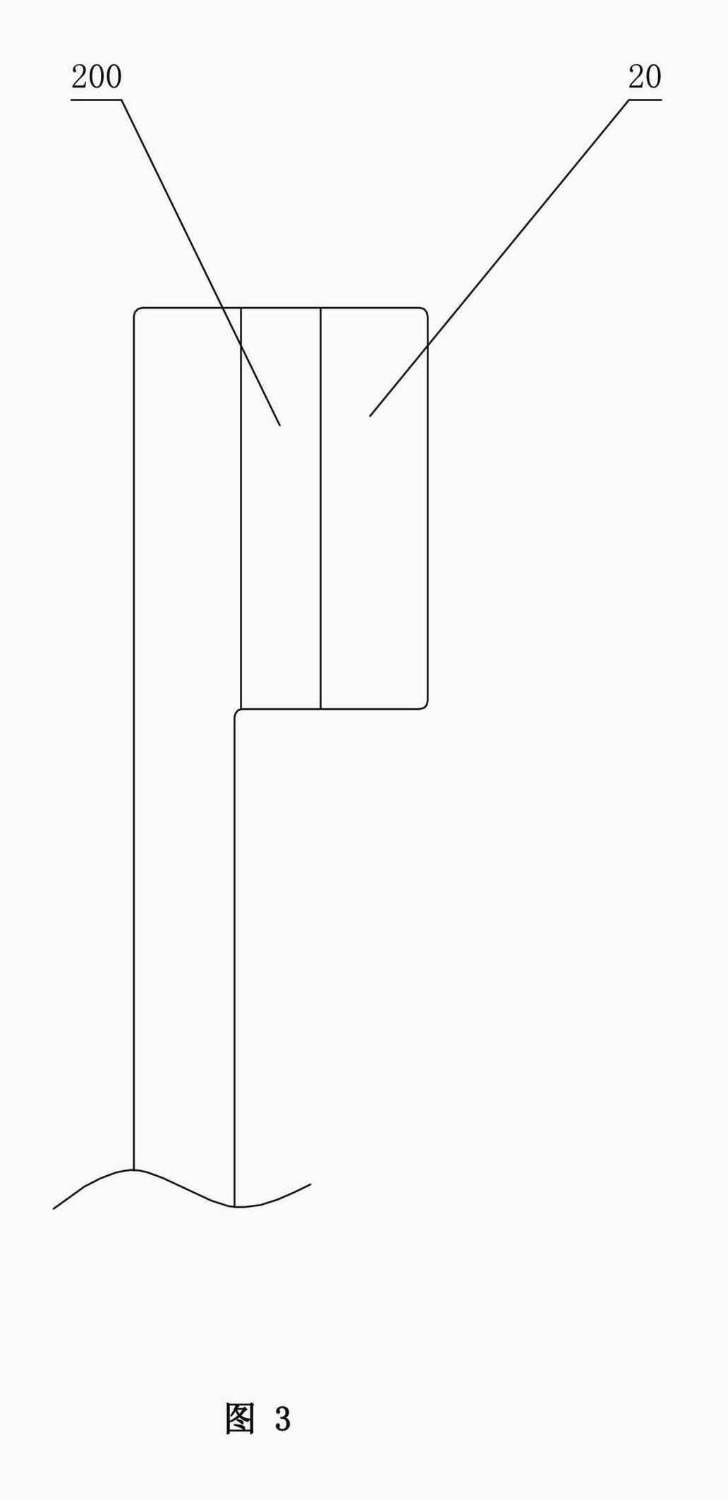
[0025] refer to figure 1 , figure 2 , image 3 , Figure 5 with Image 6 . The mandibular condylar fracture reduction spreader includes a positioning assembly, a return spring 3 and two clamp handles 1 and 2 connected by cross hinges. The front ends of the two clamp handles 1 and 2 are brace parts, and the rear ends are holding The strut portion includes the lower strut portion 20 that coincides with the mandibular notch 44 and the upper strut portion 10 that coincides with the zygomatic arch 45 corresponding to the mandibular notch 44 . The lower bracing portion 20 is generally U-shaped.

[0026] refer to figure 1 , figure 2 with Figure 4 . The positioning assembly is used to lock the distance between the upper brace part 10 and the lower brace part 20, and it includes a screw rod 50 and a nut 51 matched with the screw rod 50. The screw...


PUM


Abstract

A mandibular condyle fracture reduction dilator comprises two forceps handles which are connected in a cross hub manner. Front ends of the two forceps handles are dilating portions while rear ends of the two forceps handles are holding portions, the dilating portions comprise a lower dilating portion and an upper dilating portion, the lower dilating portion matches with a mandibular incisura, and the upper dilating portion matches with a zygomatic arch corresponding to the mandibular incisura. The mandibular condyle fracture reduction dilator further comprises a positioning component for locking a gap between the upper dilating portion and the lower dilating portion, the positioning component comprises a screw stem and a nut matching with the screw stem, the screw stem is provided with a scale graduation area for displaying the size of the gap between the upper dilating portion and the lower dilating portion, the holding portions comprise an upper holding portion and a lower holding portion which match with each other, a perforated hole is arranged on the lower holding portion, one end of the screw stem penetrates through the perforated hole to be pivotally connected with the upper holding portion, and the nut is sleeved at the other end of the screw stem in a screwed manner, and is located on the outer side of the lower holding portion. The reduction dilator can be used for directly operating in a surgical site of the maxillofacial region of a patient, exerts force on the outside of the oral cavity of the patient, leads joint clearances to be exposed easily, and is convenient in operation, an additional incision is omitted, and tissue injury is low.

Description

technical field [0001] The invention relates to a medical device, in particular to a mandibular condylar fracture reduction spreader. Background technique [0002] Mandibular condylar fractures are the most common maxillofacial fractures. After the mandibular condyle fracture, the muscle attached to the condylar end is contracted, causing the upper end of the mandibular ramus to move upward. If the fracture reduction and fixation operation is not performed in time, it will easily lead to maxillofacial deformity, joint ankylosis, and loss of occlusal function. Waiting for the sequelae, it is very harmful to the patient. [0003] Refer to attached Figure 7 . There are two common methods for mandibular condylar fracture reduction. One method is: the operator presses the mandibular retromolar bone with fingers to exert pressure on the mandible 4, so that the ramus 43 of the mandible moves downward to expose the joint space, so that it is convenient to find the broken end 41 ...

Claims


Application Information

Patent Timeline
Patent Type & Authority Applications(China)
IPC IPC(8): A61B17/02
Inventor 周剑虹
Owner 周剑虹
Why Eureka
Eureka Blog
Learn More