A crushing grinder

A grinding device and fine grinding technology, used in grain processing and other directions, can solve problems such as being easily stuck

Inactive Publication Date: 2012-07-11
卢志丽
View PDF11 Cites 8 Cited by
  • Summary
  • Abstract
  • Description
  • Claims
  • Application Information

AI Technical Summary

Problems solved by technology

[0003] The invention provides a crushing and grinding device to solve the technical problem that the existing crushing and grinding device is easy to be stuck when crushing relatively hard materials

Method used


Image

  • A crushing grinder
  • A crushing grinder
  • A crushing grinder

Examples


Embodiment Construction

[0016] The content of the present invention will be further described below in conjunction with the accompanying drawings and preferred embodiments.

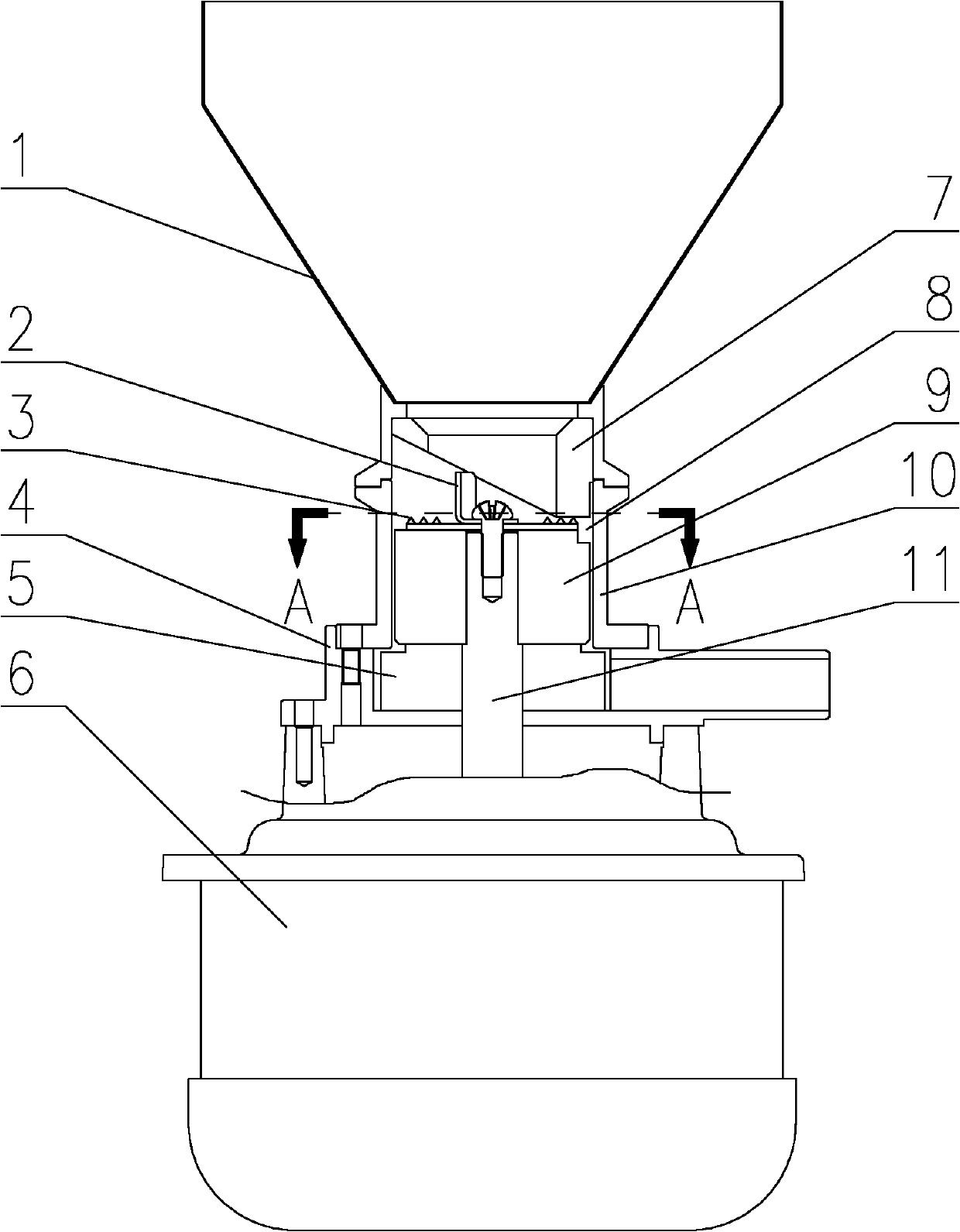
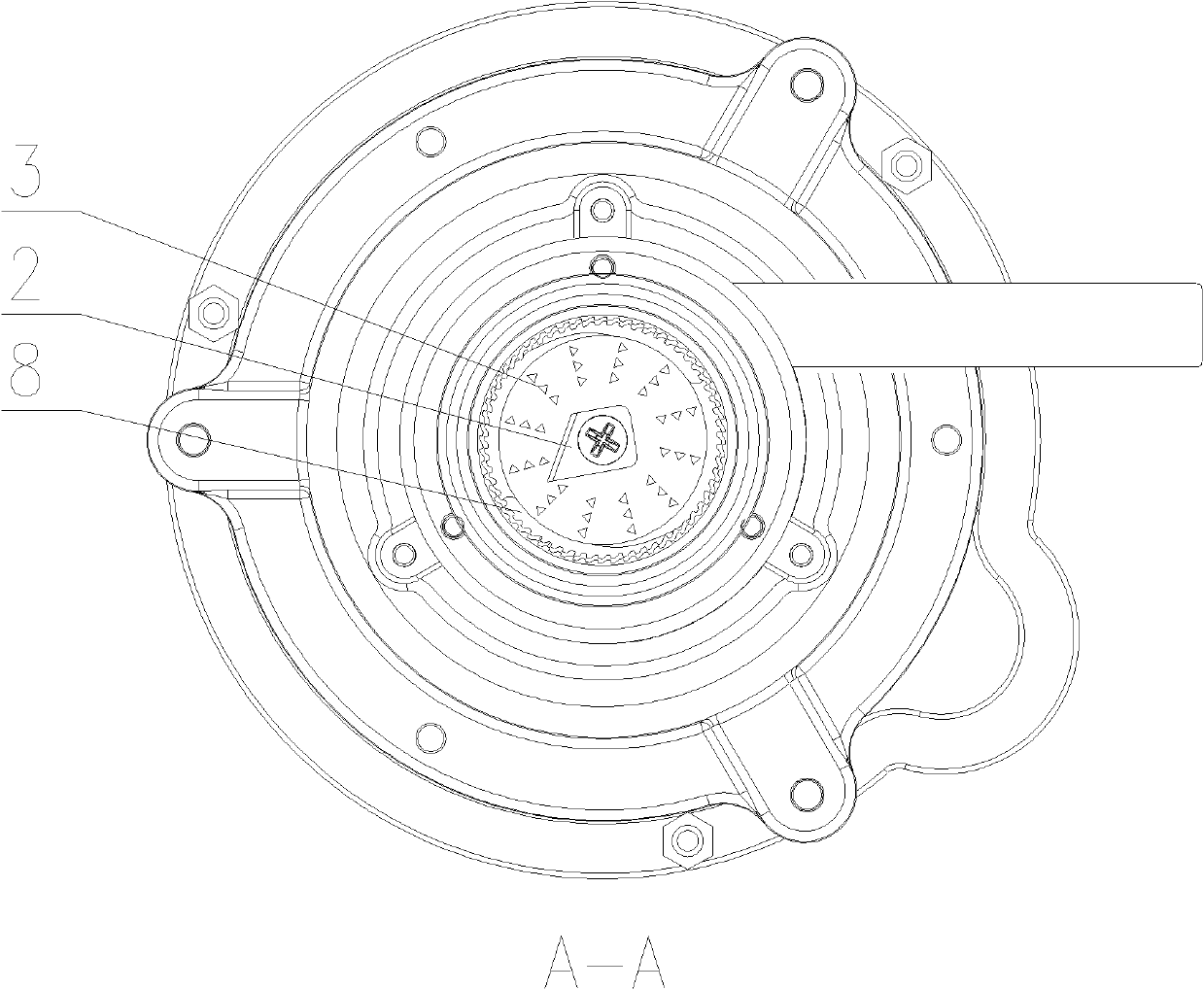
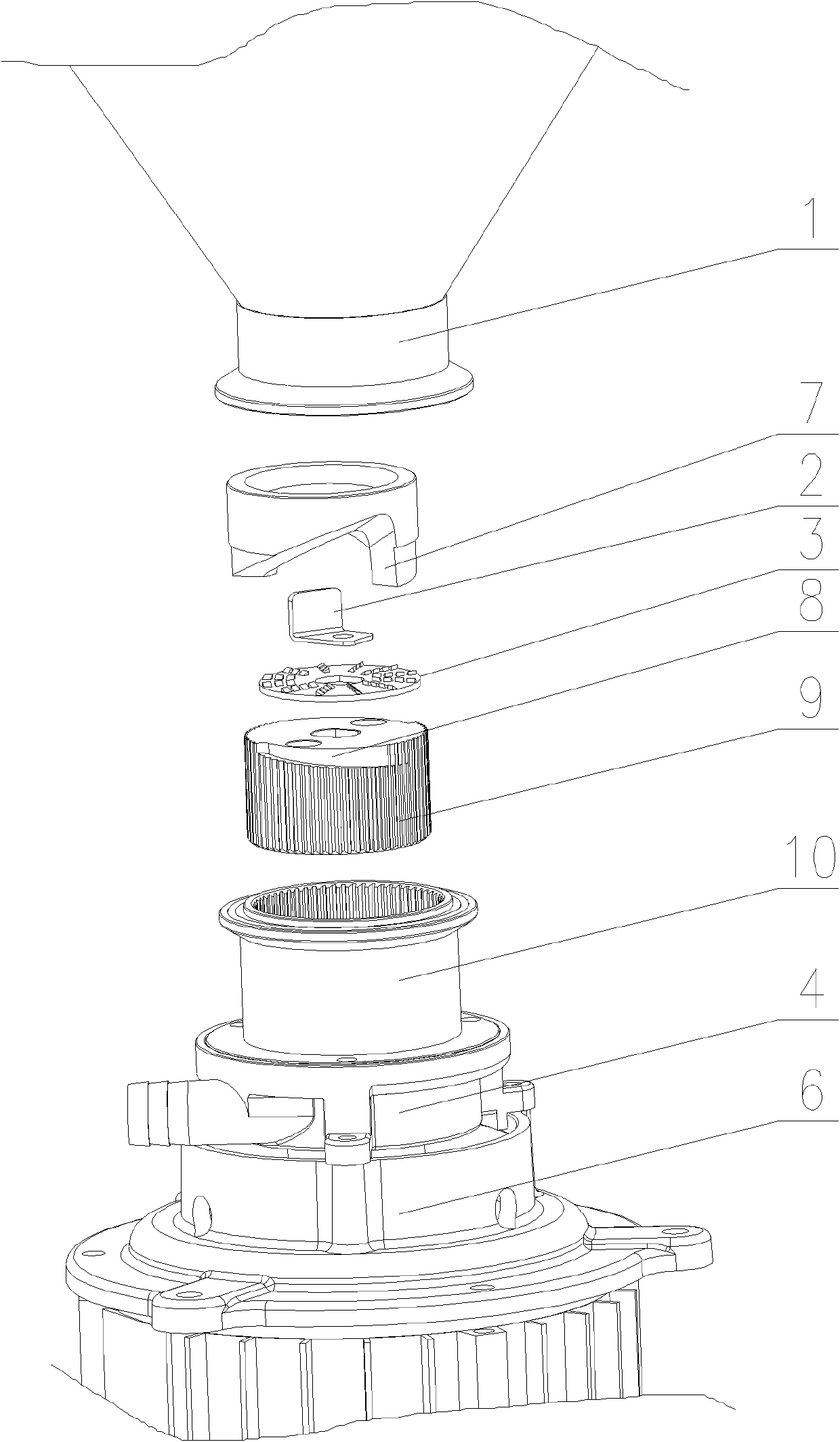
[0017] Such as figure 1 , 3 As shown, a crushing and grinding device includes a motor 6, a hopper 1, and a crushing and grinding part. The crushing and grinding part includes a coarse grinding part and a fine grinding part. The fine grinding part is composed of a moving grinding head 9 and a static grinding head 10. The coarse grinding It partly includes a cutter head 3 with a blade on the upper surface of the upper end surface of the movable grinding head 9 and a binder ring 7 arranged between the hopper 1 and the cutter head 3 . The structure of cutter head 3 is as follows: figure 2 , 3 As shown, there are multiple blades. The cutter head 3 is also provided with a shifting plate 2, which is coaxial with the motor 6, that is, the shifting plate 2 is arranged on the motor shaft 11. An impeller 5 is arranged downstream of t...


PUM


Abstract

The invention relates to a crushing grinder, which comprises a motor, a hopper and a crushing grinding part. The crushing grinding part comprises a coarse cracking part and a smooth grinding part. The smooth grinding part consists of a dynamic grinding head and a static grinding head. The coarse cracking part comprises a cutter head with a blade provided at the upper surface of the dynamic grinding head upper end and a pressing ring arranged between a hopper and the cutter head. The crushed objects are coarse cracked by their own gravity and having effect with the blade under the pressing ring effect, even hard crushed objects can be also coarse cracked by having effect with the blade for multitime and the seized phenomenon can not appear.

Description

technical field [0001] The invention relates to a crushing and grinding device. Background technique [0002] In the existing crushing and grinding device, the coarse crushing part is completed by the shearing knife on the moving grinding head, such as CN1206039C disclosed "circulation crushing and grinding device for liquid material", its device originates from the traditional colloid mill principle, and the coarse crushing part is A pair of shearing knives, when the shearing knives are coarsely crushed, they rotate and squeeze the material in a radial direction. Since the force arm is longer and the shearing knives are larger, they are easily stuck by hard objects such as dead beans, resulting in a motor stall. Contents of the invention [0003] The invention provides a crushing and grinding device to solve the technical problem that the existing crushing and grinding device is easily stuck when crushing relatively hard materials. [0004] In order to solve the above te...

Claims


Application Information

Patent Timeline
IPC IPC(8): B02C21/00
Inventor 程振盛
Owner 卢志丽
Why Eureka
Try Eureka