Blade welding clamp for impeller assembly

A technology for welding fixtures and blades, applied in welding equipment, auxiliary welding equipment, welding/cutting auxiliary equipment, etc., can solve the problems of poor positioning accuracy of blades, difficult welding, and low welding efficiency, so as to facilitate welding and improve welding work efficiency , Improve the efficiency of welding wages

Active Publication Date: 2012-07-11
常州凯度机电有限公司
View PDF6 Cites 13 Cited by
  • Summary
  • Abstract
  • Description
  • Claims
  • Application Information

AI Technical Summary

Problems solved by technology

[0003] In view of the above problems, the present invention provides a blade welding fixture for the impeller assembly, which can solve the problems of poor blad

Method used


Image

  • Blade welding clamp for impeller assembly
  • Blade welding clamp for impeller assembly
  • Blade welding clamp for impeller assembly

Examples


Embodiment Construction

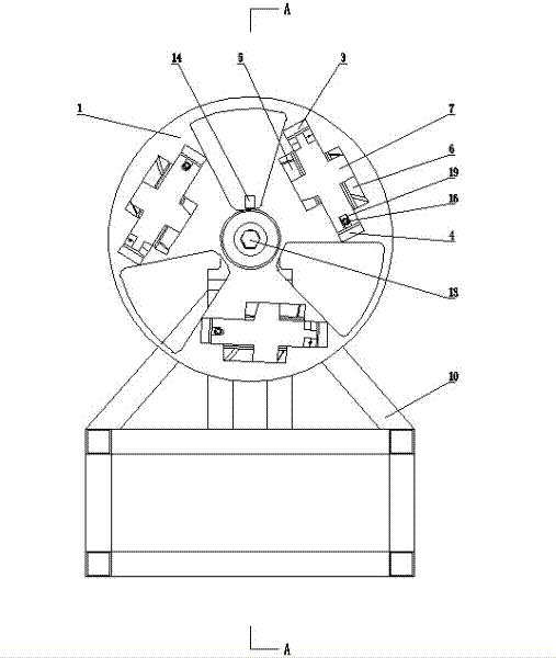
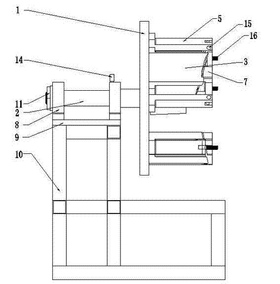
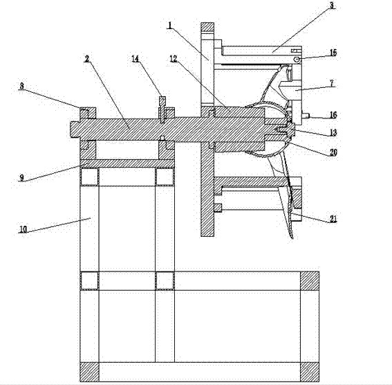
[0011] See figure 1 , figure 2 , image 3 , which includes a fixture base plate 1, on which a positioning mandrel 2 is fixed, on which a blade positioning and clamping structure is installed, three blade positioning and clamping structures are provided, and the three blade positioning and clamping structures are respectively arranged along the blade The direction of rotation is evenly arranged on the base plate 1 of the fixture. The blade positioning and clamping structure includes two L-shaped brackets 3, 4 and two positioning blocks 5, 6. The two L-shaped brackets 3, 4 are installed on the fixture bottom plate 1 facing away from each other in parallel. The upper ends of the two brackets 5, 6 pass through the cross The two positioning blocks 5 and 6 are respectively fixed on the outer sides of the two brackets 3 and 4 in parallel, and the lower surface of the cross-shaped pressing plate 7 and the upper surfaces of the two positioning blocks 5 and 6 cooperate with the profi...


PUM


Abstract

The invention provides a blade welding clamp for an impeller assembly. The blade welding clamp can solve the problems of poor blade positioning precision, welding difficulty and low welding efficiency in the welding process of the blade and the impeller assembly shell in the past. The blade welding clamp comprises a clamp bottom plate, and a positioning core rod is fixed on the clamp bottom plate. The blade welding clamp is characterized in that: three blade positioning and clamping structures are arranged on the clamp bottom plate, and the three blade positioning and clamping structures are uniformly arranged on the clamp bottom plate in the rotating direction of a blade.

Description

technical field [0001] The invention relates to the field of impeller assembly installation equipment, in particular to the field of impeller assembly installation equipment used in sewage treatment systems, in particular to the blade welding fixture of the impeller assembly. Background technique [0002] In the past, when the blades were welded to the impeller assembly shell, the impeller assembly shell was only fixed on the bottom plate through the mandrel, and then the blades were directly welded to the impeller assembly shell one by one, and the positioning and installation accuracy of the blades was poor. And it is easy to damage the blade during the welding process, thus affecting the quality of the entire impeller assembly; in addition, during the welding and installation process of the blade, because the impeller assembly shell is fixed on the bottom plate, affected by the welding position of the blade, the welding torch is not easy to enter the weld position and affe...

Claims


Application Information

Patent Timeline
IPC IPC(8): B23K37/04
Inventor 马远征黄健曹一枢
Owner 常州凯度机电有限公司
Why Eureka
Try Eureka