
Vibration suppressing method and vibration suppressing device for use in machine tool

A vibration suppression and machine tool technology, which is applied in the direction of automatic control devices, feeding devices, program control, etc., can solve problems such as inability to suppress chatter, and achieve the effect of suppressing chatter

Active Publication Date: 2012-07-11
OKUMA CORP
View PDF6 Cites 23 Cited by
  • Summary
  • Abstract
  • Description
  • Claims
  • Application Information

AI Technical Summary

Problems solved by technology

However, as mentioned above, the dynamic characteristics of the spindle system itself depend on the rotational speed of the main shaft. Therefore, when changing the rotational speed of the main shaft to the stable rotational speed for some of the calculated stable rotational speeds, The dynamic characteristics of the spindle system change, and sometimes the stable rotation speed is not the rotation speed to suppress chatter, that is, chatter cannot be suppressed

Method used


Image

  • Vibration suppressing method and vibration suppressing device for use in machine tool
  • Vibration suppressing method and vibration suppressing device for use in machine tool
  • Vibration suppressing method and vibration suppressing device for use in machine tool

Examples


Embodiment Construction

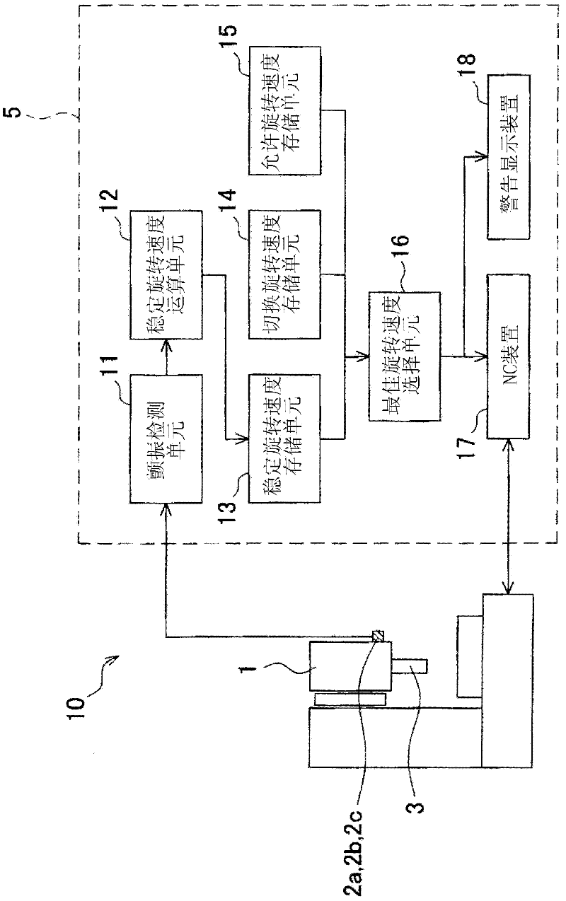
[0022] Next, a vibration suppressing method and a vibration suppressing device as one embodiment of the present invention will be described in detail with reference to the drawings.

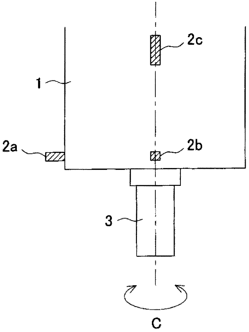
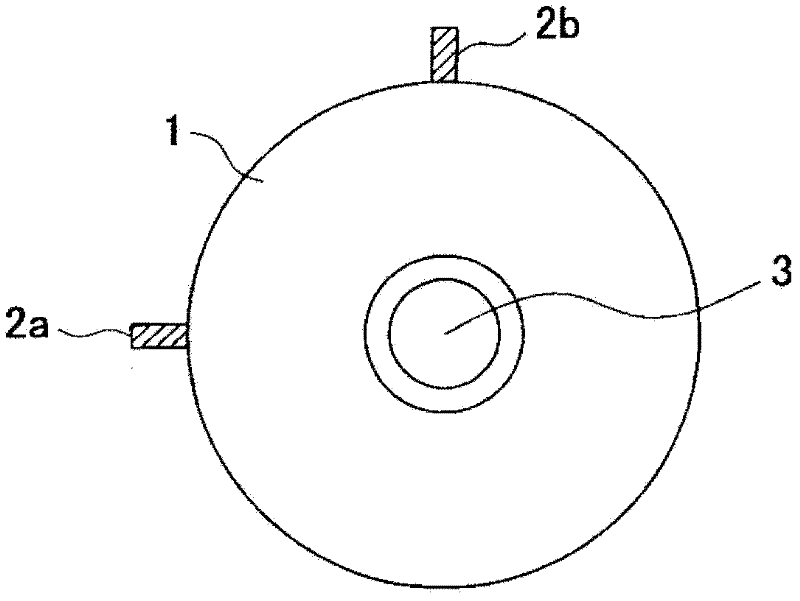
[0023] figure 1 It is an explanatory diagram showing a block configuration of the vibration suppressing device 10 . figure 2 It is an explanatory diagram showing the rotating shaft housing 1 as the object of vibration suppression from the side, image 3 It is an explanatory diagram showing the rotating shaft housing 1 from the axial direction.

[0024] The vibration suppression device 10 is used to suppress "chatter" generated by the main shaft (rotation shaft) 3, which is mounted on the main shaft housing 1 so as to be rotatable around the C-axis. The vibration suppression device 10 includes: vibration sensors 2a- 2c for detecting time-domain vibration acceleration (representing vibration acceleration on the time axis) as a characteristic value accompanying the vibration generated by the rota...


PUM


Abstract

The present invention aims to provide a vibration suppressing method and a vibration suppressing device in which an adequate stable rotation speed can be selected from the obtained stable rotation speeds without changing the dynamic characteristics so that chatter vibrations can be suppressed without fail. With the vibration suppressing method and vibration suppressing device as described above, a maximum rotation speed of the main spindle (3) and a switching rotation speed across which a dynamic characteristic of the main spindle (3) system changes are stored, then an optimum rotation speed that is a rotation speed which is not higher than the maximum rotation speed of the main spindle (3) and to which the rotation of speed of the main spindle (3) is changeable without crossing the switching rotation speed is selected from the stable rotation speeds, and the rotation speed of the main spindle (3) is changed to the optimum rotation speed selected. Accordingly, the possibilities of changing the rotation speed of the main spindle (3) to a rotation speed which cannot be attained or a rotation speed such that change of the rotation speed to that speed changes the dynamic characteristic of the main spindle (3) and thus makes it impossible to suppress ''chatter vibrations'' can be eliminated, so that the ''chatter vibrations'' can be suppressed more effectively than any existing methods.

Description

technical field [0001] The present invention relates to a vibration suppression method for suppressing chatter vibration generated during machining in a machine tool that performs machining by rotating a tool or a workpiece, and to a vibration suppression device that implements the vibration suppression method. Background technique [0002] Conventionally, a method described in Patent Document 1, for example, is known as a vibration suppression method in a machine tool for performing machining by rotating a spindle as a rotation axis. In this vibration suppression method, in order to suppress chatter vibration caused by deterioration of the finishing accuracy of the machined surface or tool breakage, etc., the natural frequency of the system that generates chatter vibration, such as the tool or workpiece, is obtained, and the natural frequency is set to The value obtained by multiplying by 60 and dividing by the number of teeth of the tool and a predetermined integer is take...

Claims


Application Information

Patent Timeline
Patent Type & Authority Applications(China)
IPC IPC(8): B23Q11/00B23Q15/12
CPCG05B2219/42344G05B19/404Y10T409/30084Y10T409/304312Y10T409/306832Y10T409/307224B23Q15/007
Inventor 上野浩
Owner OKUMA CORP
Learn More