Main shaft supporting structure of centerless grinder for grinding valve lock groove

A centerless grinding machine and spindle support technology, which is applied to machine tools, grinding machines, grinding/polishing equipment, etc. designed for grinding the rotating surface of workpieces, can solve the problems of low spindle rotation accuracy, high power consumption, and large starting torque, etc., to achieve The starting torque is small, the power consumption is small, and the effect of improving the rotation accuracy

Inactive Publication Date: 2012-07-11
WUXI QILONG MACHINE TOOL
View PDF8 Cites 7 Cited by
  • Summary
  • Abstract
  • Description
  • Claims
  • Application Information

AI Technical Summary

Problems solved by technology

[0002] The main shaft of the existing centerless grinding machine for grinding the valve lock clamp groove is directly installed in the housing through the bearings at both ends, and the main shaft needs to be in contact with the bearing when it rotates. The metal contacts each other, resulting in low rotation accuracy of its spindle

Method used


Image

  • Main shaft supporting structure of centerless grinder for grinding valve lock groove
  • Main shaft supporting structure of centerless grinder for grinding valve lock groove
  • Main shaft supporting structure of centerless grinder for grinding valve lock groove

Examples


Embodiment Construction

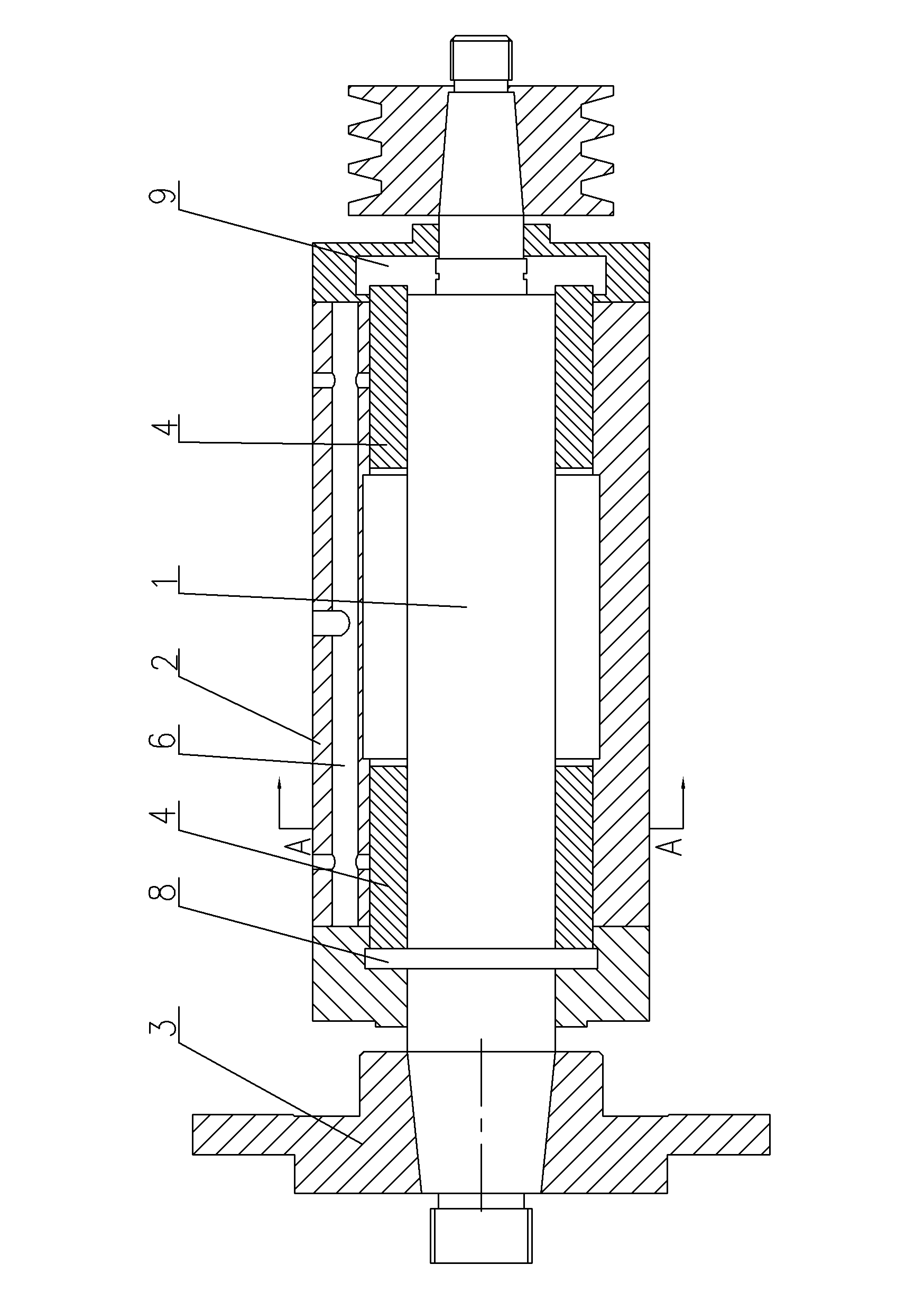
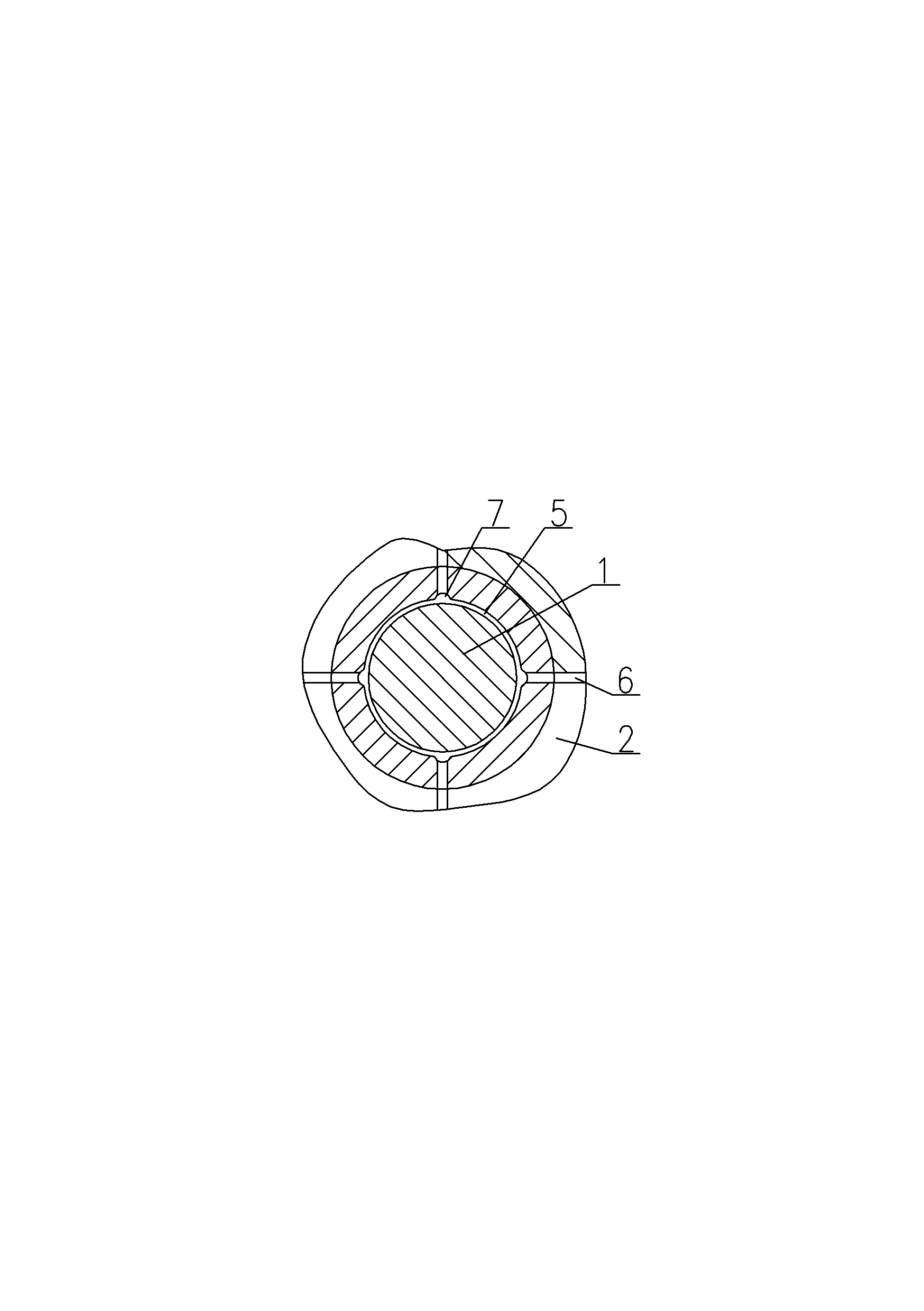
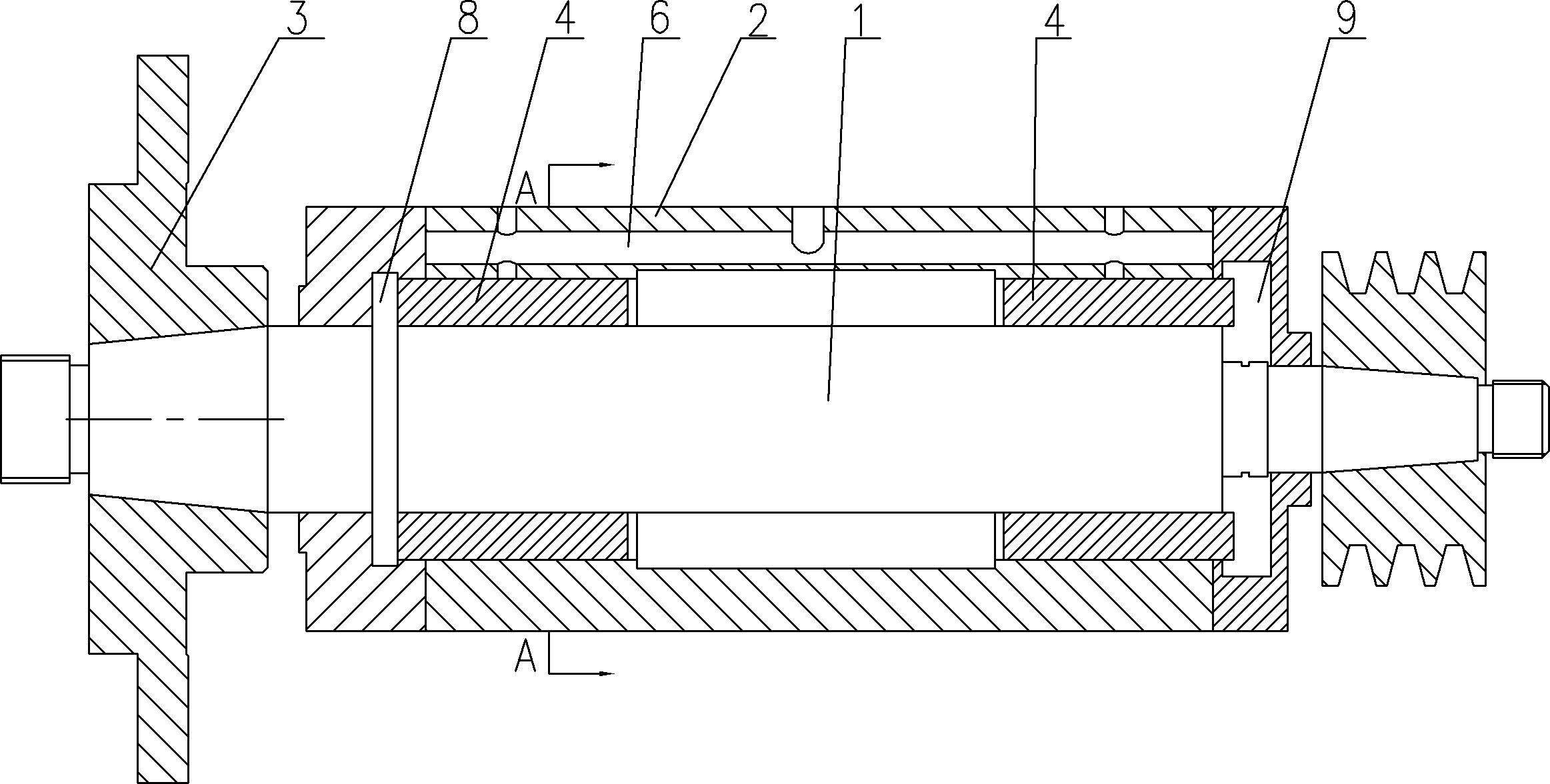
[0009] See figure 1 , figure 2 , which includes a main shaft 1, a main shaft housing 2, and a grinding wheel chuck 3. The end of the main shaft 1 is fitted with a grinding wheel chuck 3. The main shaft 1 runs through the main shaft housing 2. Both ends of the main shaft housing 2 are provided with hydrostatic oil film bearings 4. The main shaft 1 Through the inner hole 5 of the dynamic and static pressure oil film bearing 4, there is an oil passage 6 in the main shaft housing 2, and the oil passage 6 is connected to the internal oil chamber 7 of the dynamic and static pressure oil film bearing 4, and the internal oil chamber 7 is evenly distributed in the interior of the dynamic and static pressure oil film bearing 4 The inner wall of the hole 5, the inner oil chamber 7 wraps the outer edge of the main shaft 1. Both ends of the main shaft 1 are fitted with a front oil block 8 and a rear oil block 9 respectively. The front oil block 8 fits the front end of the dynamic and sta...


PUM


Abstract

The invention provides a main shaft supporting structure of a centerless grinder for grinding a valve lock groove. By the main shaft supporting structure, a main shaft is not required to contact a bearing when rotating, and is low in starting torque and power consumption and high in rotation accuracy. The main shaft supporting structure comprises the main shaft, a main shaft shell and a grinding wheel chuck, wherein the grinding wheel chuck is sleeved at the end part of the main shaft; and the main shaft penetrates through the main shaft shell. The main shaft supporting structure is characterized in that: a hydrodynamic pressure and hydrostatic pressure oil film bearing is arranged at each of the two ends of the main shaft shell; the main shaft penetrates through inner holes of the hydrodynamic pressure and hydrostatic pressure oil film bearings; an oil line is reserved in the main shaft shell, and is communicated with inner oil cavities of the hydrodynamic pressure and hydrostatic pressure oil film bearings; and the inner oil cavities are uniformly distributed on inner sidewalls of the inner holes of the hydrodynamic pressure and hydrostatic pressure oil film bearings, and wrap the peripheral surface of the main shaft.

Description

technical field [0001] The invention relates to the structural field of a centerless grinder for grinding an air door lock groove, in particular to a main shaft support structure of a centerless grinder for grinding an air door lock groove. Background technique [0002] The main shaft of the existing centerless grinding machine for grinding the valve lock clamp groove is directly installed in the housing through the bearings at both ends, and the main shaft needs to be in contact with the bearing when it rotates. The metals are in contact with each other, resulting in low rotation accuracy of its spindle. Contents of the invention [0003] In view of the above problems, the present invention provides a main shaft support structure for a centerless grinding machine for grinding valve lock clamp grooves, which enables the main shaft to rotate without contacting the bearing, has small starting torque, low power consumption, and high rotation accuracy of the main shaft. ...

Claims


Application Information

Patent Timeline
Patent Type & Authority Applications(China)
IPC IPC(8): B24B5/18B24B5/35
Inventor 游启龙
Owner WUXI QILONG MACHINE TOOL
Why Eureka
Try Eureka