Vehicle cooling system

A technology for cooling equipment and automobiles, applied in heating/cooling equipment, electric vehicles, air handling equipment, etc., which can solve problems such as cooler pressure and temperature level adjustment

Active Publication Date: 2012-07-11
HANON SYST +1
View PDF10 Cites 16 Cited by
  • Summary
  • Abstract
  • Description
  • Claims
  • Application Information

AI Technical Summary

Problems solved by technology

Therefore the pressure situation and temperature level in the cooler cannot be regulated independently of the evaporator of the vehicle air conditioning unit

Method used


Image

  • Vehicle cooling system
  • Vehicle cooling system
  • Vehicle cooling system

Examples


Embodiment Construction

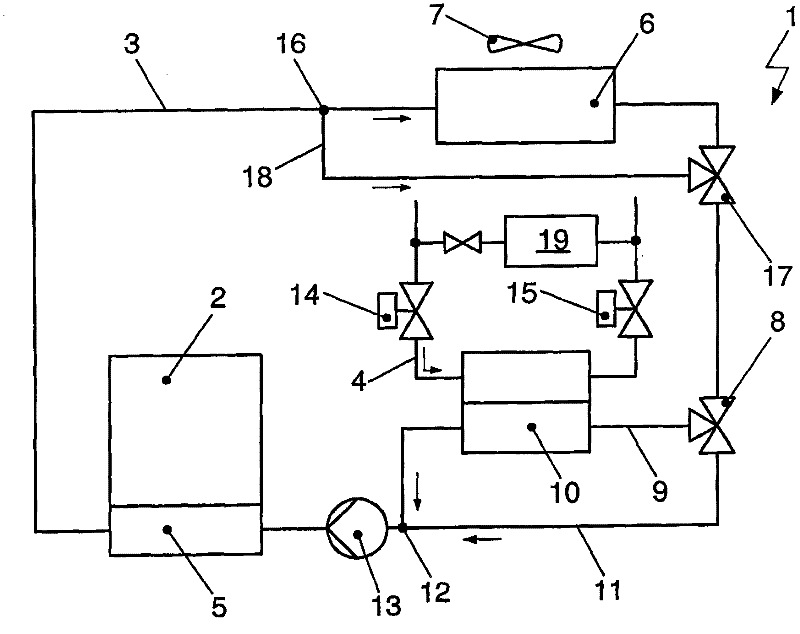
[0055] figure 1 It shows a cooling device 1 with a coolant circuit 3 which is designed to cool or dissipate the chemical energy store 2 . Instead of energy store 2 , also referred to below as battery 2 , other components of the drive train of the motor vehicle, such as an electric motor or power electronics, can likewise be coupled thermally to cooling device 1 .

[0056] The coolant circuit 3 has a pump device 13 for conveying coolant. Next to the coolant pump 13 in the direction of flow of the coolant is a heat transmitter 5 which is thermally coupled to the battery 2 . Various heat transfer methods are conceivable for this. The coolant either flows directly through the interstices formed between the battery cells and thus comes into direct contact with the surfaces of the battery cells. Alternatively, heat is transferred to the coolant via the contact surface of the housing of the accumulator 2 .

[0057] Following the battery cooler 5 in the flow direction of the coola...


PUM


Abstract

The disclosure relates to a cooling system (1) and a method for operating the cooling system (1) for cooling a battery (2) of a vehicle using a coolant circulation circuit (3). The cooling circulation circuit includes a pump device (13), a heat transmitter (5) for transferring heat between a coolant and the battery (2), a heat transmitter (6) for transferring heat between the coolant and the surroundings, and a heat transmitter (10) for transferring heat between the coolant and a refrigerant circulating in a refrigerant circulation circuit (4). The refrigerant circulation circuit (4) is designed with a heat circulation (19) and an associated expansion element. The refrigerant circulation circuit (4) includes two additional expansion elements (14, 15). The first expansion element (14) is arranged upstream of the heat transmitter (10) and the second expansion element is arranged downstream of the heat transmitter (10), with regard to the direction of the refrigerant flow. The heat transmitters (10, 19) designed as evaporators on the refrigerant side can be operated with different pressure and temperature levels.

Description

technical field [0001] The invention relates to a device with a coolant circuit for cooling a battery of a vehicle, in particular an electric vehicle or a hybrid vehicle. [0002] The invention also relates to a method for operating the cooling device. Background technique [0003] A battery with a large capacity used in an electric or hybrid vehicle is used to store electrical energy. This energy is supplied to the battery through the power terminal. In addition, in hybrid vehicles, energy can be recovered during the braking process of the vehicle. [0004] During operation, both the battery cells of the accumulator and other components of the electrical drive line, such as, for example, the electric motor and power electronics, generate heat. In particular, batteries should operate at an optimum temperature when discharging and charging. The heat generated and released must be dissipated here, since the increased operating temperature results in a very high thermal loa...

Claims


Application Information

Patent Timeline
Patent Type & Authority Applications(China)
IPC IPC(8): B60H1/32H01M10/50
CPCY02E60/12H01M10/5004B60H2001/00307H01M10/5016H01M10/5095H01M10/5079B60H1/00278B60H1/005B60L1/003B60L58/26B60L2240/34B60L2240/36B60L2240/545H01M10/613H01M10/625H01M10/6569H01M10/663Y02E60/10Y02T10/70
Inventor M·格拉夫F·维朔勒克C·雷宾格D·施罗德
Owner HANON SYST
Why Eureka
Try Eureka