
Gas-solid mixing accelerating chamber

A technology of gas-solid mixing and acceleration chamber, which is applied in the direction of conveyors, transportation and packaging, and conveying bulk materials. Ratio, prevention of accumulation and clogging, and effect of preventing bottom accumulation

Active Publication Date: 2015-06-10
XIAMEN MEIGANQIDONG MATERIAL CONVEYING ENG
View PDF3 Cites 0 Cited by
  • Summary
  • Abstract
  • Description
  • Claims
  • Application Information

AI Technical Summary

Problems solved by technology

[0003] The gas-solid mixing acceleration chamber of the prior art can only transport powdery materials. During use, when the back pressure of the transport pipeline reaches a certain value, it hinders the flow rate of the injection gas from the gas nozzle. Therefore, the gas-solid two-phase flow The mixing in the gas-solid mixing chamber is uneven, even the process of mixing and energy exchange of the gas-solid two-phase flow in the mixing chamber has not been completed, the energy loss increases, and the conveying capacity of the material decreases, which in turn causes the material to accumulate in the gas-solid mixing chamber. At the same time, in order to increase the flow rate of the gas, the power of the gas nozzle must be increased, thereby increasing energy consumption
[0004] Secondly, the gas enters from the intake pipe and is ejected from the gas nozzle, during which the gas is in a turbulent state, so the pressure loss caused is large
[0005] Again, it is impossible to observe the inside of the gas-solid mixing chamber, and it is impossible to know the state of gas-solid mixing and whether there is a failure

Method used


Image

  • Gas-solid mixing accelerating chamber
  • Gas-solid mixing accelerating chamber
  • Gas-solid mixing accelerating chamber

Examples


Embodiment Construction

[0034] The present invention will be described in detail below in conjunction with the accompanying drawings and specific embodiments.

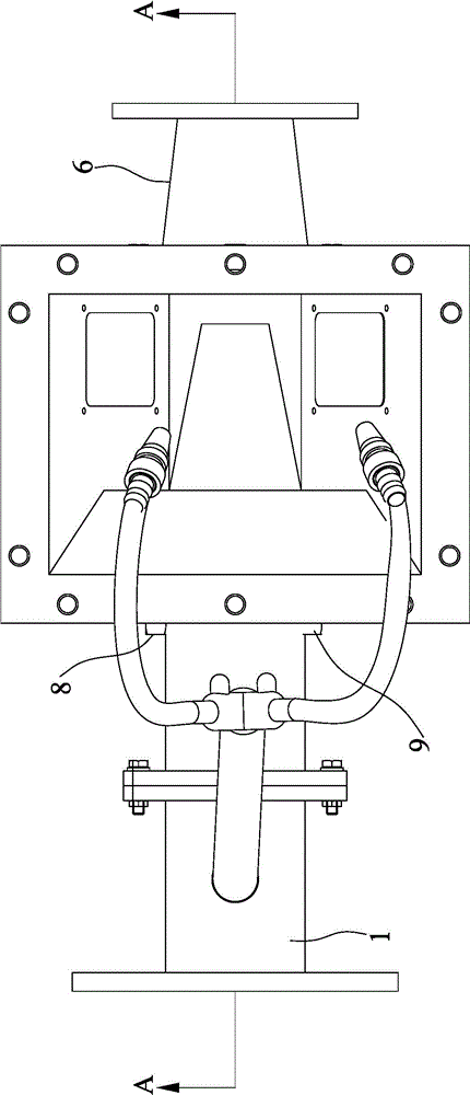
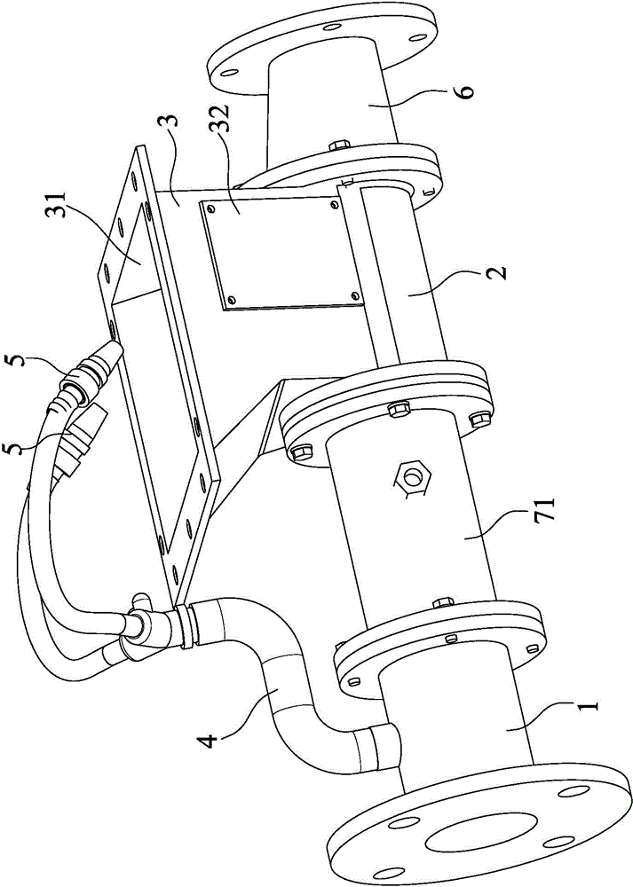
[0035] refer to Figure 1 to Figure 4 As shown, a gas-solid mixing acceleration chamber disclosed in the present invention includes a main inlet pipe 1 , a main nozzle 2 , a gas-solid mixing chamber 3 , branch pipes 4 , anti-blocking nozzles 5 and secondary nozzles 6 .

[0036] The main intake pipe 1 communicates with the main nozzle 2, the main nozzle 2 communicates with the gas-solid mixing chamber 3, the gas-solid mixing chamber 3 communicates with the secondary nozzle 6, and the secondary nozzle 6 communicates with the delivery pipeline (not shown in the figure). The structure of the main nozzle 2 is preferably an eccentric reducer structure (eccentric reducer structure, wherein the reducer is a tube with a large head gradually shrinking to a small head, also called a small head; when the eccentric reducer is erected, the projection of th...


PUM


Abstract

The invention discloses a gas-solid mixing accelerating chamber which comprises a main gas intake pipe, a main spraying nozzle, a gas-solid mixing chamber, an auxiliary spraying nozzle, a branch pipe and an anti-blocking spraying nozzle. The main gas intake pipe is communicated with the main spraying nozzle; the main spraying nozzle is communicated with the gas-solid mixing chamber, the gas-solid mixing chamber is communicated with the auxiliary spraying nozzle; the upper end of the gas-solid mixing chamber is provided with a feeding port; the main gas intake pipe is provided with the branch pipe; the branch pipe is connected with the anti-blocking spraying nozzle; and the anti-blocking spraying nozzle is arranged on the upper end of the gas-solid mixing chamber. The gas flow flows through the main gas intake pipe and enters the main spraying nozzle to be accelerated into the high-speed gas flow, then the high-speed gas flow is mixed with the material entering from the feeding port in the gas-solid mixing chamber to form the gas-solid mixed flow, and the gas-solid mixed flow is accelerated by the auxiliary spraying nozzle and enters a conveying pipe. When the backpressure of the conveying pipe increases, the material stacked in the gas-solid mixing chamber is removed by the high-speed gas flow sprayed out of the anti-blocking spraying nozzle. The gas-solid mixing accelerating chamber can effectively reduce the phenomena of gas return and backflow and has small pressure loss and low energy consumption.

Description

technical field [0001] The invention relates to a feeding device in a pneumatic conveying system, in particular to a gas-solid mixing acceleration chamber. Background technique [0002] The gas-solid mixing acceleration chamber, also known as the gas-solid injector, is the key equipment for feeding materials in the pneumatic conveying system. In the prior art, the gas-solid mixing acceleration chamber generally includes an air inlet pipe, a gas nozzle, a gas-solid mixing chamber, a blanking port, and a delivery pipeline; the air inlet pipe is directly connected to the gas nozzle, and the gas nozzle is facing the gas-solid mixing chamber. A blanking port is set above the mixing chamber, and the gas-solid mixing chamber is connected to the conveying pipeline; when in use, the gas enters the gas-solid mixing chamber from the inlet pipe and is accelerated by the gas nozzle, and then sprays into the gas-solid mixing chamber, and the solid material falls from the discharging port ...

Claims


Application Information

Patent Timeline
Patent Type & Authority Patents(China)
IPC IPC(8): B65G53/58
Inventor 苏骑
Owner XIAMEN MEIGANQIDONG MATERIAL CONVEYING ENG
Learn More