Hollow filler beam column and production method thereof

A hollow filling and manufacturing method technology, applied in the field of beams and columns, can solve the problems of high manufacturing and use costs, and achieve the effects of low installation cost, low production cost and wide application range

Inactive Publication Date: 2012-07-11
邱成飞
View PDF6 Cites 8 Cited by
  • Summary
  • Abstract
  • Description
  • Claims
  • Application Information

AI Technical Summary

Problems solved by technology

[0004] The purpose of the present invention is to provide a method for manufacturing air intake of hollow filled beams and columns, so as to

Method used


Image

  • Hollow filler beam column and production method thereof
  • Hollow filler beam column and production method thereof
  • Hollow filler beam column and production method thereof

Examples


Embodiment Construction

[0030] In order to make the object, technical solution and advantages of the present invention more clear and definite, the present invention will be further described in detail below with reference to the accompanying drawings and examples.

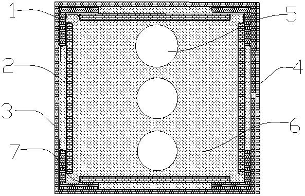
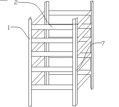
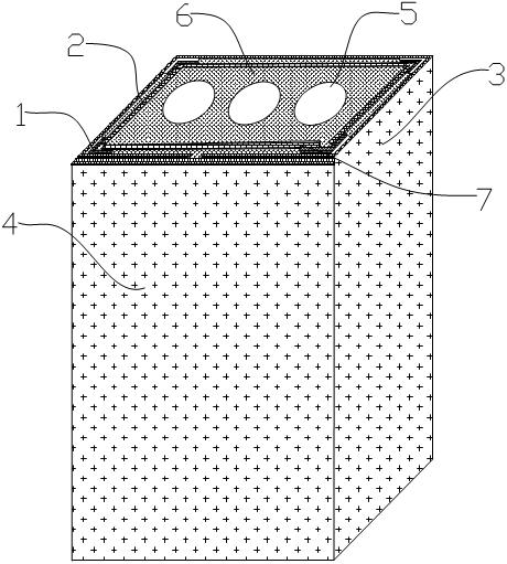
[0031] The hollow filled beam column of the present invention, such as figure 1 As shown in the schematic cross-sectional view of the hollow filled beam column of the present invention, the hollow filled beam column provided by the present invention includes an angle iron 1, a connecting plate 2, a first stainless steel sheet 3, a second stainless steel sheet 4, a hollow tube 5 and a foam filler 6 , wherein the first stainless steel sheet 3 and the second stainless steel sheet 4 together form the shell of the hollow filled beam column. In the present embodiment, the quantity of angle iron 1 is four, and the length is 6 meters; The quantity of connecting plate 2 is 200, long 10 centimeters, wide 4 centimeters; Its thickness of the first s...


PUM


Abstract

The invention discloses a hollow filler beam column and a production method thereof. The hollow filler beam column comprises iron angles, connecting plates, a shell, hollow pipes and foam fillers, wherein adjacent iron angles are welded through the connecting plates to form a skeleton of the filler beam column; the shell is closely arranged on the skeleton in a wrapping way; the hollow pipes evenly penetrate through the skeleton; and the foam fillers are filled between the hollow pipes and the shell. Compared with the existing building beam column, since a hollow structure and a foam filling structure are adopted, the dead weight of a column body is greatly reduced and the installation cost and the manufacturing cost of the column body are effectively saved. Besides, since the filling structure and a skeleton structure are adopted, the strength of the hollow filler beam column is equivalent to the strength of the beam column in the prior art and the application scope is quite wide.

Description

technical field [0001] The invention relates to a beam column, in particular to a hollow filled beam column and a manufacturing method thereof. Background technique [0002] Most of the existing building beams and columns are reinforced concrete structures or steel structures. Due to the high price and large consumption of materials such as steel and cement, such beams and columns are expensive to manufacture. In addition, due to the high density of steel and cement, the self-weight of the beams and columns is also very large. Due to their high self-weight, the beams and columns for this type of construction must either be poured directly on the construction site, or large-scale construction such as cranes is required. Mechanical equipment is installed, resulting in very high installation costs. In addition, the use of such building beams and columns usually adds a lot of load to the construction project itself. Correspondingly, the foundation strength of the project mu...

Claims


Application Information

Patent Timeline
IPC IPC(8): E04C3/29E04C3/36E04G21/14
Inventor 邱成飞
Owner 邱成飞
Why Eureka
Try Eureka