Lamp

A technology of lamps and light-emitting surfaces, applied in the field of lamps of substitutes, can solve problems such as complicated wiring

Inactive Publication Date: 2012-07-11
HITACHI APPLIANCES INC
View PDF10 Cites 8 Cited by
  • Summary
  • Abstract
  • Description
  • Claims
  • Application Information

AI Technical Summary

Problems solved by technology

[0007] In Patent Document 1 image 3 In the lamp shown, the light reflected by the side wall of the reflector is also reflected to the lower side than the surface on which the LED substrate is mounted by making the shape of the reflector into an inverted truncated cone shape. In order to reduce the amount of light, LEDs are placed on the reflector, so multiple LEDs cannot be placed on the same board, and the wiring for installation and power supply becomes very complicated.

Method used


Image

  • Lamp
  • Lamp
  • Lamp

Examples


Embodiment 1

[0031] In this embodiment, an example of a reflector structure that performs light distribution control will be described.

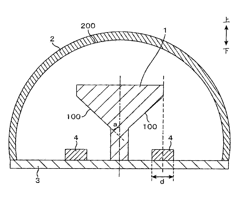
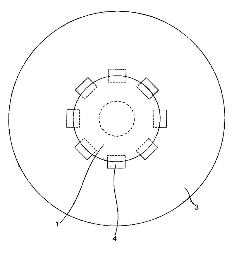
[0032] figure 1 It is a side cross-sectional view of the light emitting unit according to Example 1 of the present invention. The basic structure is a reflector structure 1 (reflecting structure), LED board 3 on which LED 4 is mounted, LED 4 (light emitting body) as a light source, and cover 2 . exist figure 1 Among them, LED4 has a light-emitting surface on the upper surface. The light emitted from the LED 4 has higher directivity than a fluorescent lamp or an incandescent lamp. Therefore, in the LED 4 having a light emitting surface on the upper surface, the light is concentrated in the upward direction, and the light intensity in the upward direction is higher than that in the side and the like.

[0033]The reflector structure 1 has a shape in which an inverted truncated cone is superimposed on a cylinder. That is, the reflector structure 1 has a...

Embodiment 2

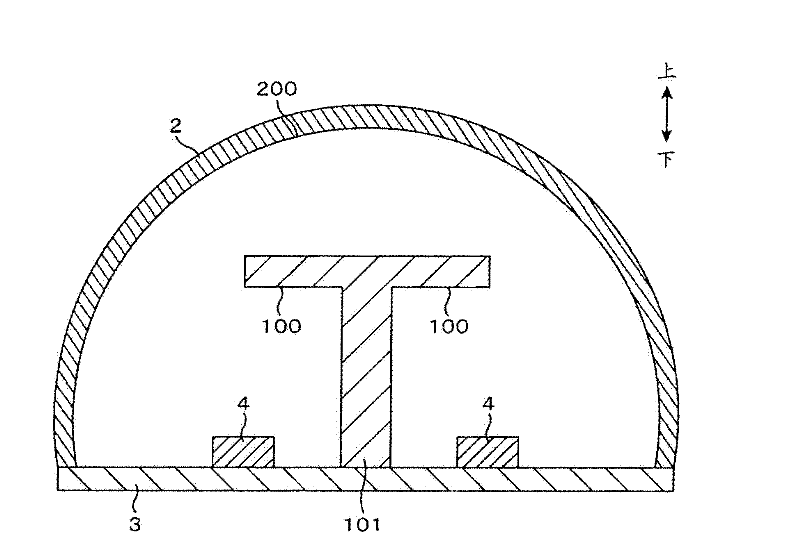
[0048] In this second embodiment, a mode different from that of the first embodiment will be described. image 3 It is a side cross-sectional view of a light emitting unit according to Example 2 of the present invention. The reflector structure 101 has a shape in which a circular plate is attached to a cylinder. The cross section of the reflector structure 101 has a T-shape when viewed from the side. That is, the reflector structure 101 has a shape in which the outer diameter remains constant from the lower end to the upper end, increases near the upper end, and then remains constant from near the upper end to the upper end. The facing surface 100 is formed on the lower surface of the circular plate (the lower surface of the T-shaped arm portion.

[0049] Although the structure of the reflector structure 101 is different from that of the first embodiment, other properties are the same as those of the first embodiment. By changing the shape of the reflector structure 101, it...

Embodiment 3

[0051] In this third embodiment, a mode different from that of the first embodiment will be described. Figure 4 It is a side cross-sectional view of a light emitting unit according to Example 3 of the present invention. The reflector structure 102 has a shape in which a hemisphere is attached to a cylinder with its curved surface facing downward. That is, the reflector structure 102 has a shape in which the outer peripheral diameter is constant from the lower end to the upper side, gradually increases from the middle to the upper side, and then the outer peripheral diameter is constant from the vicinity of the upper end to the upper end. The opposite surface 100 is formed on a hemispherical curved surface.

[0052] Although the structure of the reflector structure 102 is different from that of the first embodiment, other properties are the same as those of the first embodiment. The upper surface of the reflector structure 102 may also be concave. By changing the shape of the...


PUM


Abstract

The invention relates to a lamp. Prior lamps adopting LEDs having the following problems that the emission of side lights is weak and the emission of backward light nearly does not exist. And light scatters backward in the same using condition with a filament lamp. Moreover, if the LEDs are not on the same substrate, problems of complicated wire arrangement in installation and power supply also exists. The lamp in the invention is characterized in that a plurality of LEDs (4) are arranged on the same LED substrate (3) and is provide with a cover (2) covering the whole face of the LED substrate (3) and having light admitting capacity and scattering capacity. A reflector structural body (1) is arranged above the light emitting face of the LEDs (4) and in the cover (2). The reflector structural body (1) is on the same normal with the light emitting face and covers at least one part of the light emitting face.

Description

technical field [0001] The present invention relates to a lamp (illumination device), and particularly relates to a lamp provided with a semiconductor light-emitting element such as an LED (Light Emitting Diode) as a light source and mainly used as a substitute for an incandescent lamp. Background technique [0002] In recent years, in order to prevent global warming, energy saving has been promoted, and in the field of lighting, research and development of lamps using LEDs have been conducted as substitutes for conventional incandescent lamps. Compared with existing incandescent lamps, lamps using LEDs have higher energy conversion efficiency. When considering expanding the use of lamps using LEDs, it is desirable to be able to use existing incandescent lamp sockets as they are, and it is desirable to be able to use them in the same way as conventional incandescent lamps. [0003] LEDs have strong rectilinear propagation properties when light is emitted, and when used in t...

Claims


Application Information

Patent Timeline
Patent Type & Authority Applications(China)
IPC IPC(8): F21S2/00F21V13/04F21Y101/02
Inventor 饭塚亚纪子中里典生畠山笃史野村和男
Owner HITACHI APPLIANCES INC
Why Eureka
Try Eureka