LED fluorescent lamp with adjustable light projecting angle

An LED fluorescent lamp and angle technology, applied in the field of LED lighting, can solve the problems of low light efficiency utilization rate and single light projection direction, and achieve the effect of overcoming light efficiency waste, reducing volume, and simplifying the assembly process

Inactive Publication Date: 2012-07-11
惠州市天然光电科技有限公司
View PDF14 Cites 2 Cited by
  • Summary
  • Abstract
  • Description
  • Claims
  • Application Information

AI Technical Summary

Problems solved by technology

[0004] The present invention aims at the shortcomings of the existing LED fluorescent tubes with adjustable light projection angles such as single light projection direction and low light efficiency utilization rate, and provides an LED fluorescent lamp with adjustable light projection angle and more flexible installation and use.

Method used


Image

  • LED fluorescent lamp with adjustable light projecting angle
  • LED fluorescent lamp with adjustable light projecting angle
  • LED fluorescent lamp with adjustable light projecting angle

Examples


Embodiment Construction

[0029] The present invention will be described in detail below in conjunction with the accompanying drawings and embodiments.

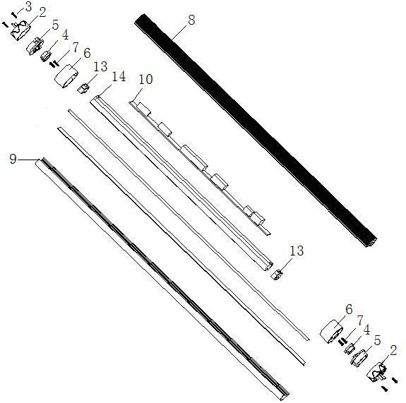
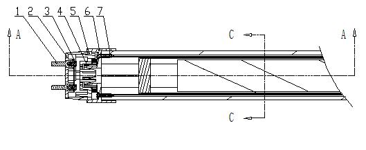
[0030] The present invention is based on an assembly structure of LED fluorescent tubes, as attached Figure 1-2 , the fluorescent tube includes a lamp body and lamp holders 6 installed at both ends of the lamp body, and a lamp holder cover assembly. The lamp holder cover assembly is installed outside the lamp holder. With the rotation of the lamp holder cover assembly relative to the lamp holder, the adjustment of the projection angle of the lamp is realized.

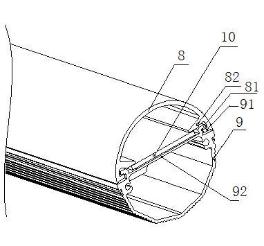
[0031] Such as Figure 6-10 , The lamp base cover assembly includes a lamp base cover 2, a rotating piece 5 and a positioning ring 4, the rotating piece 5 is installed in the lamp base cover and fixed on the lamp base cover 2 by screws; the positioning ring 4 is then loaded into the lamp base cover 2, The lower end of the positioning ring 4 is provided with a bayonet 41, and the lamp holde...


PUM


Abstract

The invention relates to an LED fluorescent lamp, which comprises a lamp body, lamp holders and lamp holder cover components. The lamp holders are disposed at two ends of the lamp body, each lamp holder cover component consists of a lamp holder cover, a rotating plate and a positioning ring, each rotating plate and the corresponding positioning ring are sequentially mounted on the corresponding lamp holder cover, the upper end of each positioning ring is an annular sheet, bumps are disposed at the edge of each annular sheet, annular sheet portions are exposed out of the lamp holder covers and penetrate into the lamp holders deeply, and the bumps correspond to grooves on inner circumferences of the lamp holders. When the lamp body rotates relative to the lamp holder cover components, the annular sheet portions of the positioning rings elastically deform, the bumps rotate around the grooves of the lamp holders, and the light projecting position of the lamp body is changed by a certain angle when each bump rotates into a corresponding groove. Limiting columns are arranged on the rotating plates, correspond to limiting grooves on the lamp body, and limit rotation angles of the lamp holder cover components and the lamp body. The light projecting angle of the fluorescent lamp tube is adjustable, waste of a lighting effect is avoided, a light source is sufficiently utilized, simultaneously, the LED fluorescent lamp is mounted in a mode consistent to that of a traditional fluorescent tube, a support does not need to be replaced, other parts do not need to be added, and the LED fluorescent lamp is convenient and speedy in replacement.

Description

[0001] The present invention involves the field of LED lighting technology, which is specifically referring to a LED fluorescent lamp structure with adjustment angle. Background technique [0002] LED has unparalleled highlights, energy saving and environmental protection, etc. Almost all lighting lamps began to use LED as a light source, and continuously innovated on the basis of the original traditional lighting technology. Of courseexception.The adjustable LED fluorescent lamp tube that can be adjusted in the light angle perfectly inherits the excellent characteristics of the traditional fluorescent lamp, and made a major breakthrough on the original basis, which is more prominent;Utilization, life is more than 6 times the fluorescent lamp tube, and there are no tedious problems such as tubes, tunnels, and inspirations. [0003] The green environmentally friendly LED light source is adopted, with high output and soft light, which is conducive to protecting vision and concentrate...

Claims


Application Information

Patent Timeline
Patent Type & Authority Applications(China)
IPC IPC(8): F21S2/00F21V17/16F21V19/02F21V23/00F21Y101/02F21K9/27F21Y115/10
Inventor 莫罕波洪光岱韩党伟刘举旗
Owner 惠州市天然光电科技有限公司
Why Eureka
Try Eureka