Centering adjustment method for wheel sets of locomotive test stand and traction force meter stand thereof

An adjustment method and traction force technology, which are applied in the direction of measuring the traction/propulsion power of vehicles, railway vehicle testing, etc., can solve the problems of affecting the test progress, unstable operation, unsafe operation, etc., achieve flexible expansion and adjustment of the coupler, and improve the life of the reducer. , the effect of improving the test efficiency

Active Publication Date: 2012-07-11
CRRC DALIAN INST CO LTD
View PDF6 Cites 20 Cited by
  • Summary
  • Abstract
  • Description
  • Claims
  • Application Information

AI Technical Summary

Problems solved by technology

[0004] 1 The tested locomotive is positioned with a single coupler, such as figure 1 As shown, the positioning reference is set at the coupler center line of the single coupler 25, and the locomotive wheel pair 14 is difficult to sit on the apex of the track wheel pair 15, and the center of the upper and lower wheel pairs tends to deviate horizontally. When the locomotive 13 starts to run, due to the function of the buffer of the locomotive coupler, the locomotive has a large serial movement in the horizontal direction. With the acceleration or deceleration of the locomotive 13, frequent collisions between the couplers will affect the test.
[0005] 2 The locomotive under test is positioned with anchor pile structure, such as figure 2 As shown, the anchor pile 26 can only passively withstand the pulling force provided by the tested locomotive 13
[0008] 1) The tested locomotive is positioned with a single coupler. Due to the gap between the coupler buffer and the coupler of the tested locomotive, the acceleration or deceleration of the locomotive frequently collides between the couplers, and the locomotive has a large front-to-back movement in the horizontal direction. Safe, unstable, affecting the test
[0009] 2) The tested locomotive adopts the anchor pile structure, which cannot provide tension or pressure. The horizontal position of the tested locomotive cannot be adjusted, and the vertical alignment position deviation of the center of the locomotive wheel and the track wheel cannot be adjusted immediately.
[0010] 3) The installation connection of the tension and pressure sensor is an easy-to-break part. Generally, there is no anti-break mechanical and electrical secondary safety protection device, and there is a lack of safety protection.
[0011] 4) With the center line of the coupler at one end as the positioning reference, it is not easy to install an automatic wheelbase adjustment device for this structure

Method used


Image

  • Centering adjustment method for wheel sets of locomotive test stand and traction force meter stand thereof
  • Centering adjustment method for wheel sets of locomotive test stand and traction force meter stand thereof
  • Centering adjustment method for wheel sets of locomotive test stand and traction force meter stand thereof

Examples


Embodiment Construction

[0047] The present invention is further described now in conjunction with accompanying drawing.

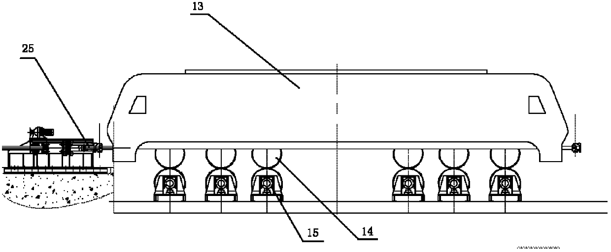
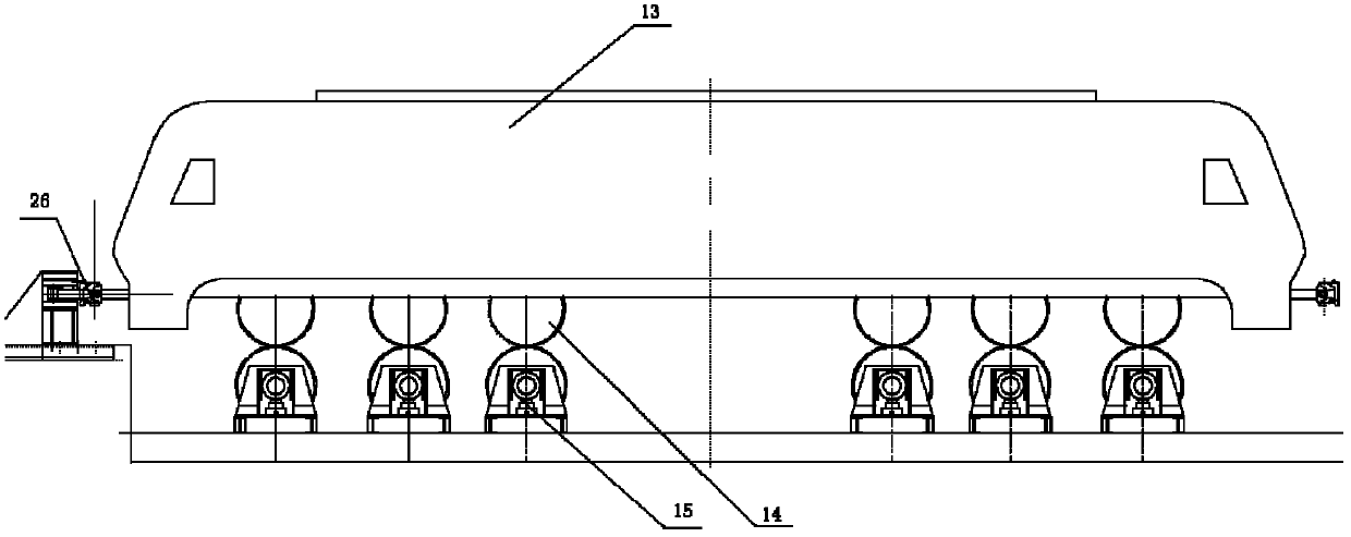
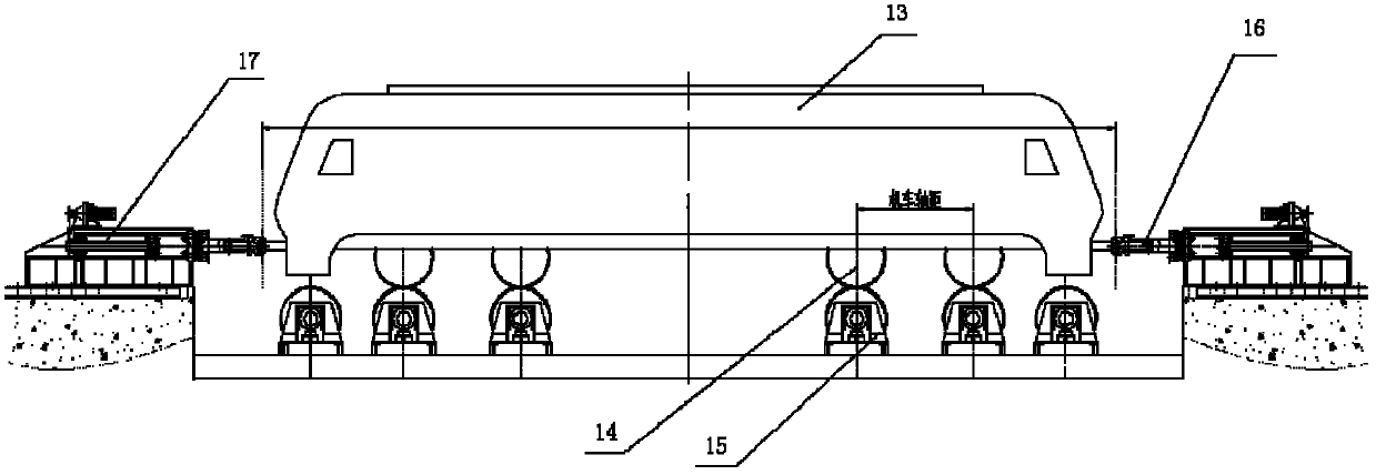
[0048] image 3 It is a schematic diagram of the positioning of the retractable coupler with double traction gauges for the tested locomotive. According to the coupler center distance of the locomotive to be tested, the retractable coupler position of the A-end traction meter platform 17 is preset. The test locomotive 13 moves slowly, and its coupler is locked with the retractable coupler of the A-end traction meter platform 17, and the whole weight of the locomotive 13 is seated on the track wheel 15 through the locomotive wheel 14 through the lifting mechanism. If there is a gap between the coupler and the coupler, adjust it so that the coupler is under pressure, and the force display shows a negative value; return the traction force meter 16 at the B end, start the telescopic coupler, and lock it with the coupler of the locomotive under test. For the centering of the wheel pa...


PUM


Abstract

The invention relates to a centering adjustment method for wheel sets of a locomotive test stand and a traction force meter stand thereof. In order to enable all locomotive wheels of a locomotive to completely fall into corresponding rail wheels in foundation pits of the test stand, during test, the centers of the locomotive wheels are required to be kept perpendicularly centered with the centers of the rail wheels, and the locomotive is required to run in location mode in the horizontal direction, and thus the tested locomotive can be ensured to run stably and safely on the test stand. The centering adjustment method of the test stand of the locomotive comprises the following steps of 1 selecting the central lines of the foundation pits of the rail wheels to serve as location reference lines; 2 adopting a double-traction force meter stand to serve as the test stand; 3 performing secondary centering adjustment on the locomotive wheel sets and the rail wheel sets; and 4 providing the same pre-tightening force for a car coupler of the tested locomotive, and offsetting or reducing the horizontal displacement of the locomotive caused by deformation of the car coupler buffer. A speed reducer shaft of the traction force meter stand is parallel with a crew, a nut is screwed on the screw, a chain wheel on the speed reducer shaft is connected with a chain wheel on the nut through a chain, and one end of the screw is connected with a traction force measurement device.

Description

technical field [0001] The invention relates to a wheel alignment adjustment method of a locomotive test bench and a traction force meter thereof. Background technique [0002] The locomotive enters the test bench through the guide beam device, and the locomotive wheel is centered up and down with the pre-placed rail wheel in the foundation pit of the test bench. The locomotive coupler is hung on the coupler on the traction meter platform and positioned. run on an infinitely long track. In the test, due to the existence of the coupler buffer device of the tested locomotive and the existence of the gap between the couplers, the horizontal position of the tested locomotive changes with the traction force, and the front and rear serial shifts occur. As the locomotive accelerates or decelerates, the coupler frequently collides, which affects the operation of the locomotive. System stability, safety and traction force measurement accuracy. [0003] Existing technical solutions:...

Claims


Application Information

Patent Timeline
Patent Type & Authority Applications(China)
IPC IPC(8): G01M17/08G01L5/13
Inventor 刘和才周作顺王磊
Owner CRRC DALIAN INST CO LTD
Why Eureka
Try Eureka