Near-field delay calibration method for channels of broadband thinned array radar

A sparse array and channel technology, applied in the field of near-field delay calibration of broadband sparse array radar channels

Active Publication Date: 2012-07-11
THE 724TH RES INST OF CHINA SHIPBUILDING IND
View PDF4 Cites 13 Cited by
  • Summary
  • Abstract
  • Description
  • Claims
  • Application Information

AI Technical Summary

Problems solved by technology

Due to the large antenna aperture, although the far-field calibration method is simple to implement,

Method used


Image

  • Near-field delay calibration method for channels of broadband thinned array radar
  • Near-field delay calibration method for channels of broadband thinned array radar
  • Near-field delay calibration method for channels of broadband thinned array radar

Examples


Embodiment Construction

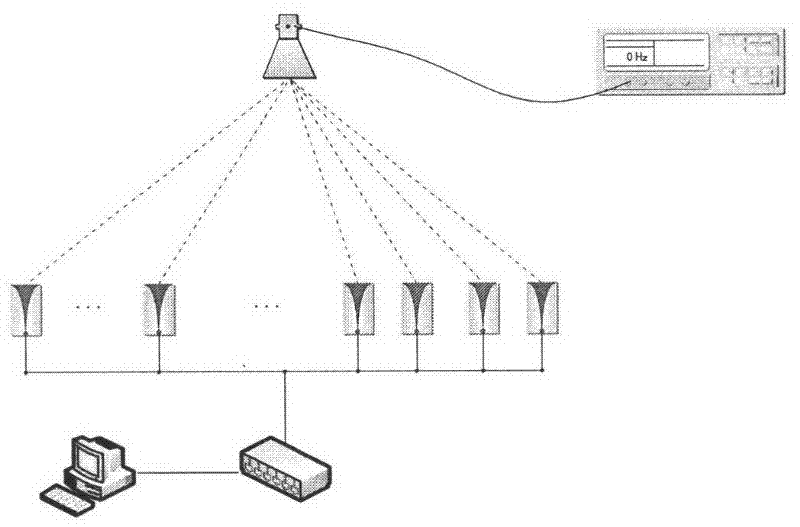
[0009] The near-field delay calibration structure of large sparse array radar channels is as follows: figure 1 shown. These include: signal sources, radiating horn antennas, large sparse array radar antenna receiving units, and calibration algorithms. Measure the distance from the near-field horn antenna to each unit through a laser ranging device, and obtain the spatial delay difference from the horn antenna to each antenna unit; set up a signal source in the near-field to radiate a FM signal with a certain bandwidth and frequency, and sparsely distribute the array The radar antenna receives the radiation signal of the signal source, collects the signals of each channel, and uses the calibration algorithm to calculate the channel delay difference; the channel delay difference minus the space delay difference, that is, the large sparse array radar channel delay difference.

[0010] Let the signal of the nth channel of acquisition input be

[0011] X ...


PUM


Abstract

The invention relates to a near-field delay calibration method for channels of a broadband thinned array radar, which comprises the following steps of: erecting a signal source in the near-field environment to radiate frequency-modulated signals with a certain frequencies and broadbands, receiving the signals radiated by the signal source by using a large-scale thinned array antenna to be calibrated and acquiring the signals received by each channel; converting the channel signals into a frequency domain by using a dechirping technology; acquiring a high-precision estimation of a frequency difference value of the channel signals in the frequency domain by using a frequency difference value high-precision estimation method so as to obtain a delay estimation initial value of the channel signals; correcting a phase difference value of the channels by using a time domain delay high-precision estimation method to obtain a delay calibration value of the channels; and calibrating a delay filter of a signal processing unit of the thinned array radar by the calibration value.

Description

technical field [0001] The invention relates to a method for calibrating the near-field time delay of a broadband sparse array radar channel. In particular, it relates to the technique of calibrating the delay difference and phase difference inside the channel by measuring the delay difference between channels of the wideband sparse array radar under near-field conditions. Background technique [0002] Large-scale broadband sparse antenna element array radar has become the development direction of security search radar technology because of its strong angular resolution and range resolution. In order to improve the angular resolution and operating range, the number of elements of the array antenna is continuously increasing; as a direct result of improving the range resolution, the radar uses a broadband signal with a larger instantaneous bandwidth. The premise of obtaining the high-resolution capability of radar detection is the consistency performance among the multiple c...

Claims


Application Information

Patent Timeline
IPC IPC(8): G01S7/40
Inventor 徐超
Owner THE 724TH RES INST OF CHINA SHIPBUILDING IND
Why Eureka
Try Eureka