
Eureka
For R&D, Eureka makes reading and utilizing patents & technical documents easy.
Eureka AIR
Designed for self-driven R&D workflows. Generate viable solutions, solve complex R&D challenges, empower your innovation with AI.

Eureka Materials
Designed for material experts only. Revolutionize your material R&D, from search, analyze, to developing new materials.

TechResearch
Generate reliable direction feasibility study reports for your R&D in just a few steps.

TechSeek
Discover and master advanced knowledge NOW. Basics, ideas, possibilities, all at once.

TechMind
As an expert in R&D Theories, TechMind can generates customized viable solutions instantly.

TechRisk
Analyze your overall solution with one click, know your potential R&D risks in advance.

TechMonitor
Get weekly tech updates, stay abreast of the latest tech innovations and key insights.
Low current fuse
A technology for fuses and electrodes used in the manufacture of these fuses, land grid arrays and surface mount microcurrent fuses
- Summary
- Abstract
- Description
- Claims
- Application Information
AI Technical Summary
Problems solved by technology
Method used
Image

Examples
example
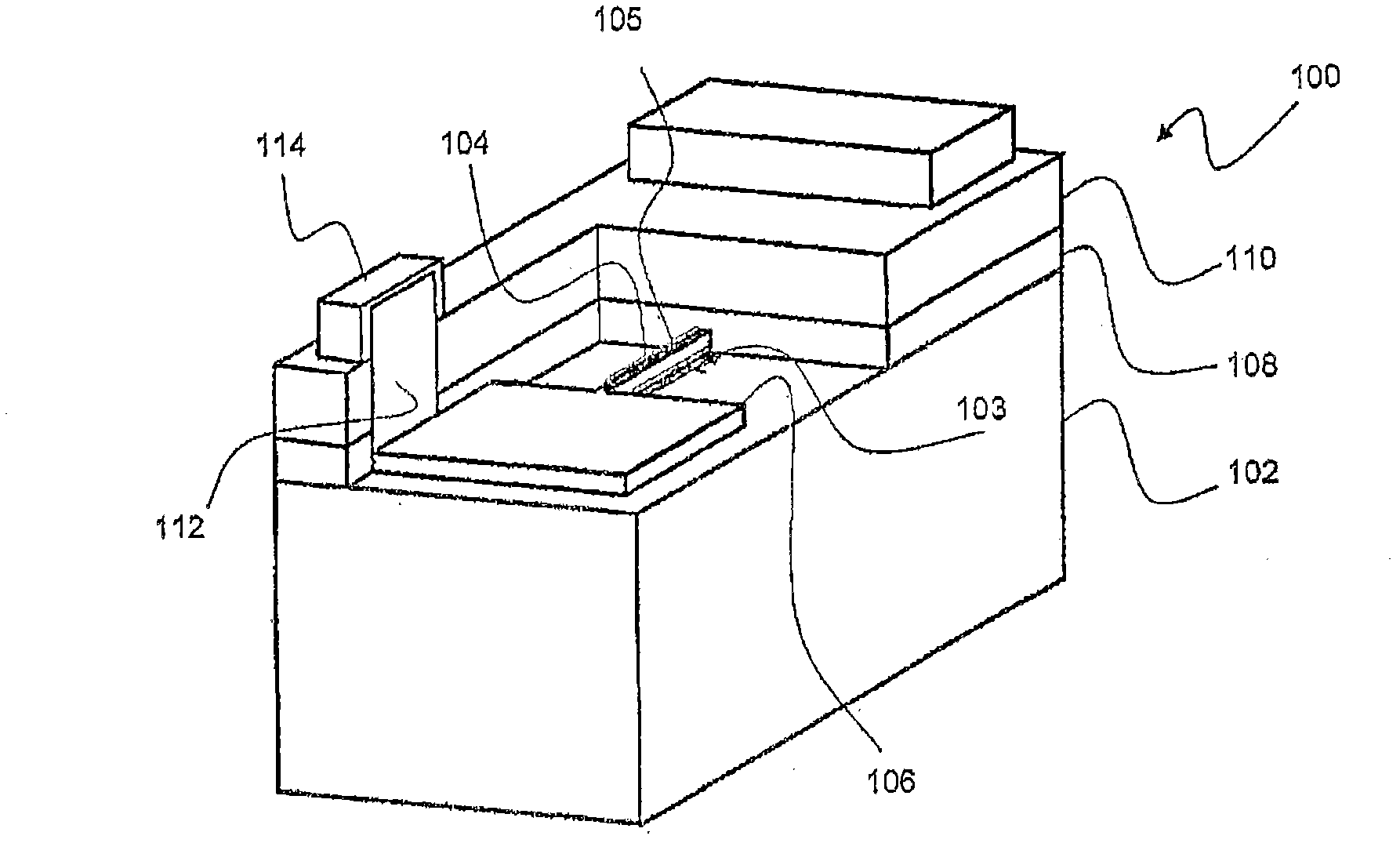
[0078] refer to figure 1 , the following preferred embodiments are intended to provide a low current fuse 100 rated to blow if exposed to a maximum current in excess of between 0.1 and 0.5 amps.
[0079] The required dimensions are precisely reproducible and the fuse needs to have a high electromigration resistance. Such precise low-current fuses can be obtained by depositing fuse element 104 comprising nickel or copper traces 3 to 20 μm (micrometers) wide, with a predetermined thickness in the range of 0.2 to 2 microns, and preferably There is an integral pad 106 .
[0080] A thin layer of tantalum 103 is preferably deposited first to obtain good adhesion and prevent interaction between the substrate 102 and the nickel fuse element 104 .
[0081] Glass is selected as the substrate 102 . It should be noted that various glasses, ceramics or glass-ceramics may be used.
[0082] The thin layer 103 of tantalum, which is typically several hundred Angstroms thick, can be deposit...
PUM
 Abstract
Description
Claims
Application Information
 - R&D Engineer
- R&D Manager
- IP Professional
- Industry Leading Data Capabilities
- Powerful AI technology
- Patent DNA Extraction
Browse by: Latest US Patents, China's latest patents, Technical Efficacy Thesaurus, Application Domain, Technology Topic, Popular Technical Reports.
© 2024 PatSnap. All rights reserved.Legal|Privacy policy|Modern Slavery Act Transparency Statement|Sitemap|About US| Contact US: help@patsnap.com