Leakage communication system with fault location and method

A leaky communication and fault location technology, applied in the field of leaky communication systems, can solve the problems that the coverage field strength cannot meet the requirements, the working environment is poor, and the leaky cables cannot be monitored and maintained in advance, so as to reduce the number of equipment and connectors, and improve the Stability and reliability, the effect of shortening the time for troubleshooting

Inactive Publication Date: 2012-07-11
北京达因瑞康电气设备有限公司
View PDF4 Cites 6 Cited by
  • Summary
  • Abstract
  • Description
  • Claims
  • Application Information

AI Technical Summary

Problems solved by technology

But the ensuing problem is that the length of the cable is long, there are many joints, and it is prone to failure. Therefore, the stability of the performance of the leaky cable plays an important role in the operation of the wireless communication system.
[0003] Leaky cables are generally suspended on the roadway wall, and the working environment is very harsh due to the influence of dust, water, etc.
In particular, due to loose joints, water ingress, and cable sheath damage and corrosion, etc., the transmission loss of the leaky cable may increase, and the coverage field strength cannot meet the requirements, which will eventually lead to a decrease in communication quality or even interruption.
[0004] It is also difficult for maintenance personnel to carry out inspection and maintenance work on leaky cables. Therefore, leaky cables with problems cannot be monitored and maintained in advance.
[0005] There are more and more leakage communication applications in the coverage area, but there is no leakage communication platform system with self-test function

Method used


Image

  • Leakage communication system with fault location and method
  • Leakage communication system with fault location and method

Examples


Embodiment Construction

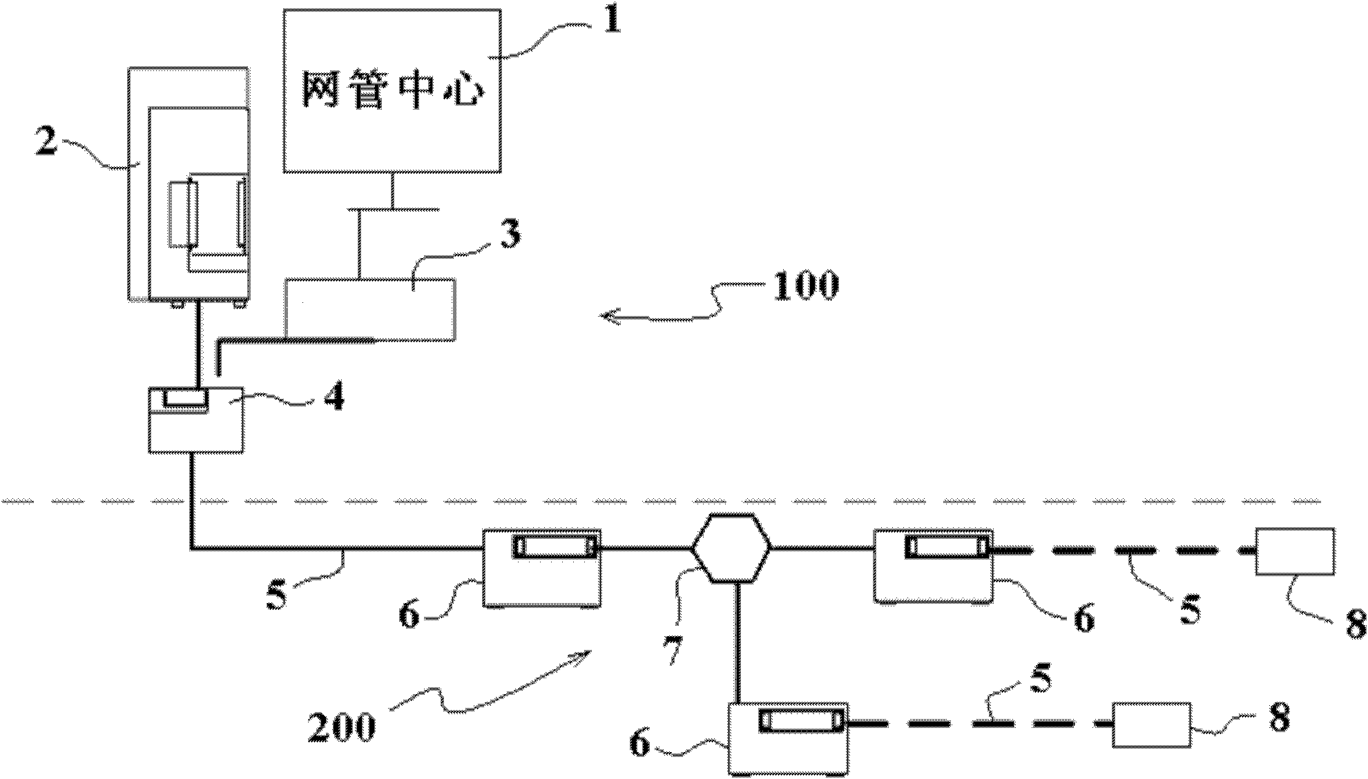
[0025] System communication function:

[0026] like figure 1 As shown, the downlink signal (base station → coverage area) sent by the channel machine in the base station 2 goes down through the leaky cable 5, and at the same time, the uplink signal (coverage area → base station) sent by the walkie-talkie in the coverage area is transmitted to the base station 2 through the leaky cable 5.

[0027] The function of the isolator 4 is to ensure the non-physical connection between the ground safety area 100 and the coverage area non-safety area 200 .

[0028] According to the attenuation parameters of the leaky cable 5, in one embodiment, a repeater 6 is installed every 400-500m in the coverage area to increase the amplitude of the bidirectional signal.

[0029] According to the actual situation of the roadway in the coverage area, a distributor 7 is installed at the branch point for the coverage of different roadways, and a load 8 is installed at the end of the leaky cable coverag...


PUM


Abstract

The invention discloses a leakage communication system with fault location, comprising a base station for sending and receiving signals, repeaters for amplifying signals and a leakage cable for signal coverage. The system is characterized by comprising an equipment self-checking device for judging a single-machine state and a system-inspecting device for judging the state of the leakage cable and displaying the state of the system. A channel machine in the base station is connected with the leakage cable in a coverage area by an isolator; repeaters are arranged on the leakage cable in the coverage area at intervals of 400-550m; distributors are arranged at branch positions of roadways in the coverage area and connected with a plurality of subsequent repeaters by the leakage cable; every subsequent repeater is connected with more subsequent subsequent repeaters by the leakage cable; and load for signal matching is arranged at a coverage terminal of leakage cable. The system is capable of automatically judging operation state of the system, initiatively offering fault alarm and locating a fault onto equipment or the cable, thereby creating convenience for maintenance of users.

Description

technical field [0001] The invention relates to a leakage communication system and method with fault location, in particular to a coverage area self-diagnosis leakage communication platform system and method, which can automatically detect the working status of the amplification equipment in the system and the quality of the leakage cable. Background technique [0002] The biggest advantage of the leakage system in the coverage area is the whole chain coverage, ensuring that there are no blind spots in the coverage area, which is also impossible for PHS, wifi and other systems. But the ensuing problem is that the cable length is long, there are many joints, and it is prone to failure. Therefore, the stability of the performance of the leaky cable plays an important role in the operation of the wireless communication system. [0003] Leaky cables are generally suspended on the roadway wall, and the working environment is very harsh due to the influence of dust and water. In ...

Claims


Application Information

Patent Timeline
Patent Type & Authority Applications(China)
IPC IPC(8): H04W24/04H04W88/18H04B5/00
Inventor 潘盾苏建亚李明刘庆江
Owner 北京达因瑞康电气设备有限公司
Why Eureka
Try Eureka