
LED driving apparatus

A LED drive and transistor technology, applied in the field of LED drive devices, can solve the problems of switching noise of switching elements for dimming, failure to actively promote replacement of self-fluorescent lamps, poor operation of surrounding electrical equipment, etc., and achieve the effect of reducing noise

Inactive Publication Date: 2012-07-11
SANKEN ELECTRIC CO LTD
View PDF5 Cites 3 Cited by
  • Summary
  • Abstract
  • Description
  • Claims
  • Application Information

AI Technical Summary

Problems solved by technology

[0004] LED lighting devices, although having excellent characteristics as described above, have not been actively promoted such as replacement from fluorescent lamps
One of the reasons for this is that noise may be generated from the LED lighting device, and this noise may cause malfunction of the surrounding electrical equipment.
Even in conventional LED lighting devices, there are concerns about switching noise when the switching element for dimming is turned on and off, and noise when the current flowing through the LED group load is turned on / off

Method used


Image

  • LED driving apparatus
  • LED driving apparatus
  • LED driving apparatus

Examples


Embodiment Construction

[0027] Hereinafter, preferred embodiments of the present invention will be described with reference to the drawings.

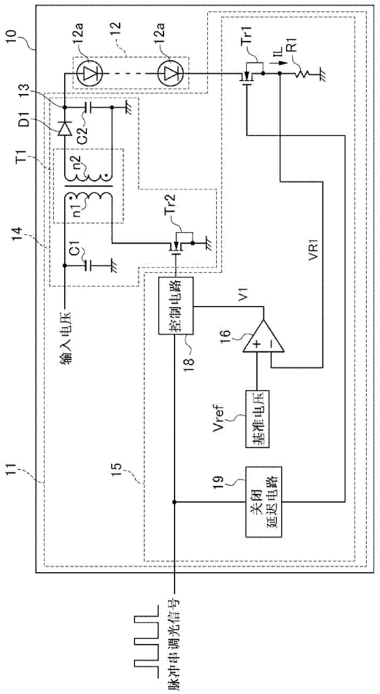
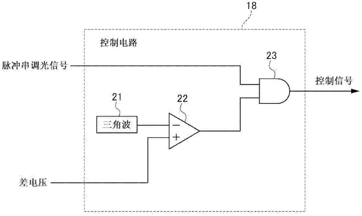
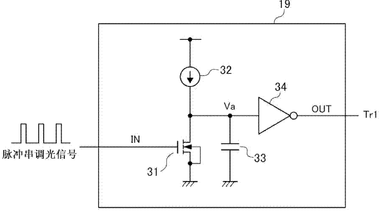
[0028] figure 1 It is a circuit diagram showing an LED driving device according to an embodiment of the present invention. The LED driving device 11 is connected to an LED unit 12 including at least one LED 12 a in order to convert input power into desired DC power and supply it to an LED unit (LED group load) 12 . The LED driving device 11 and the LED unit 12 constitute the LED lighting device 10 .

[0029] The LED unit 12 is connected to the LED driving device 11 . The LED unit 12 is formed by connecting a plurality of LEDs 12a in series. In addition, about the LED unit 12, one LED 12a may be sufficient. In addition, instead of the LED 12a, a light emitting load other than the LED may be used as long as it is an element that emits light according to the flowing direct current.

[0030] The LED drive device 11 is configured to include a power conversion ...


PUM


Abstract

The invention provides an LED driving apparatus capable of reducing noises generated from an LED lighting apparatus. The LED driving apparatus that converts input power into direct-current power and feeds the power to an LED unit, includes: a first transistor that turns current flowing to the LED unit between on-and-off; an LED current detector that detects the current flowing to the LED unit; a controller that outputs a control signal controlling power to be fed to the LED unit, based on an error between a detected voltage obtained by the LED current detector and a burst dimming signal to dim the LED unit; and a second transistor that controls the power to be fed to the LED unit, based on the control signal output from the controller, wherein the first transistor is turned on; based on the burst dimming signal, and wherein the first transistor is turned off, based on a delay signal that is delayed at a predetermined time from the burst dimming signal.

Description

technical field [0001] The invention relates to an LED driving device, in particular to an LED driving device for performing pulse train dimming. Background technique [0002] In recent years, attention has been paid to LED (Light Emitting Diode) lighting, which has the characteristics of relatively long life and low power consumption, as lighting equipment that replaces bulb-type fluorescent lamps and straight-tube fluorescent lamps from the viewpoint of ecology and energy saving, and has been promoted. develop. The LED lighting device includes: a power supply unit (LED driving device) that converts input power into desired DC power and supplies it to an LED group load; and an LED group load in which a plurality of LEDs are connected in series. The power supply unit has a switching element for supplying electric power to the LED group load, and a dimming switching element connected in series to the LED group load. In the conventional LED driving device, in synchronization...

Claims


Application Information

Patent Timeline
IPC IPC(8): H05B37/02
CPCH05B33/0842H05B33/0815H05B33/0824H05B45/44H05B45/385H05B45/325H05B45/395H05B45/327
Inventor 木村研吾
Owner SANKEN ELECTRIC CO LTD
Learn More