
Method and device for intelligently controlling brightness of flash of camera

An intelligent control and camera technology, applied in energy-saving control technology, lighting devices, lamp circuit layout, etc., can solve problems such as inconsistency, poor image quality, waste of resources, etc., and achieve low cost, simple structure, and energy-saving effects

Inactive Publication Date: 2012-07-11
CENTRINO BEIJING VIDEO TECH
View PDF5 Cites 55 Cited by
  • Summary
  • Abstract
  • Description
  • Claims
  • Application Information

AI Technical Summary

Problems solved by technology

[0004] 1. The use of high-brightness LED lights leads to the waste of the entire resource, which leads to the problem of light pollution
[0005] 2. Cameras in different monitoring locations generally have different monitoring locations and ambient light conditions. They all adopt constant brightness white light LEDs and white light shields. On the one hand, they cannot effectively meet the lighting requirements of the cameras.
On the other hand, at the same monitoring point, the ambient light may also change continuously, resulting in poor supplementary light effects such as constant brightness white LEDs, and it is difficult to achieve a relatively ideal effect for the captured image
[0006] In addition, the current method of supplementing light with a constant brightness light source is usually based on the photosensitive element of the photoresistor to judge the illuminance of the light, but the photoresistor has the defect of inaccurate and inconsistency in judging the lighting conditions, and it brings a lot of inconvenience to the construction work
In addition, for some places, such as places where effective power supply cannot be provided, continuous lighting such as white LEDs with constant brightness cannot be satisfied, resulting in poor image quality and high noise at night (when the light is insufficient)

Method used


Image

  • Method and device for intelligently controlling brightness of flash of camera
  • Method and device for intelligently controlling brightness of flash of camera
  • Method and device for intelligently controlling brightness of flash of camera

Examples


Embodiment Construction

[0028] Embodiments of the present invention are described in detail below, examples of which are shown in the drawings, wherein the same or similar reference numerals designate the same or similar elements or elements having the same or similar functions throughout. The embodiments described below by referring to the figures are exemplary only for explaining the present invention and should not be construed as limiting the present invention.

[0029] The following disclosure provides many different embodiments or examples for implementing different structures of the present invention. To simplify the disclosure of the present invention, components and arrangements of specific examples are described below. Of course, they are only examples and are not intended to limit the invention. Furthermore, the present invention may repeat reference numerals and / or letters in different instances. This repetition is for the purpose of simplicity and clarity and does not in itself indicat...


PUM


Abstract

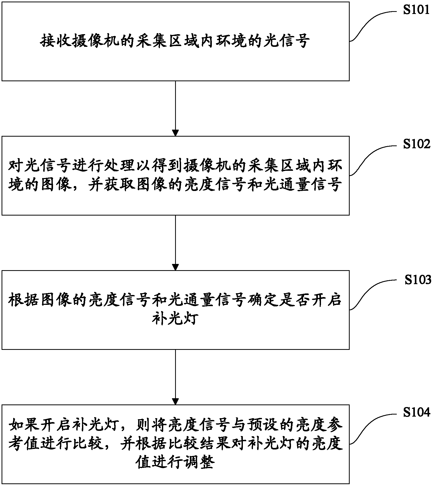
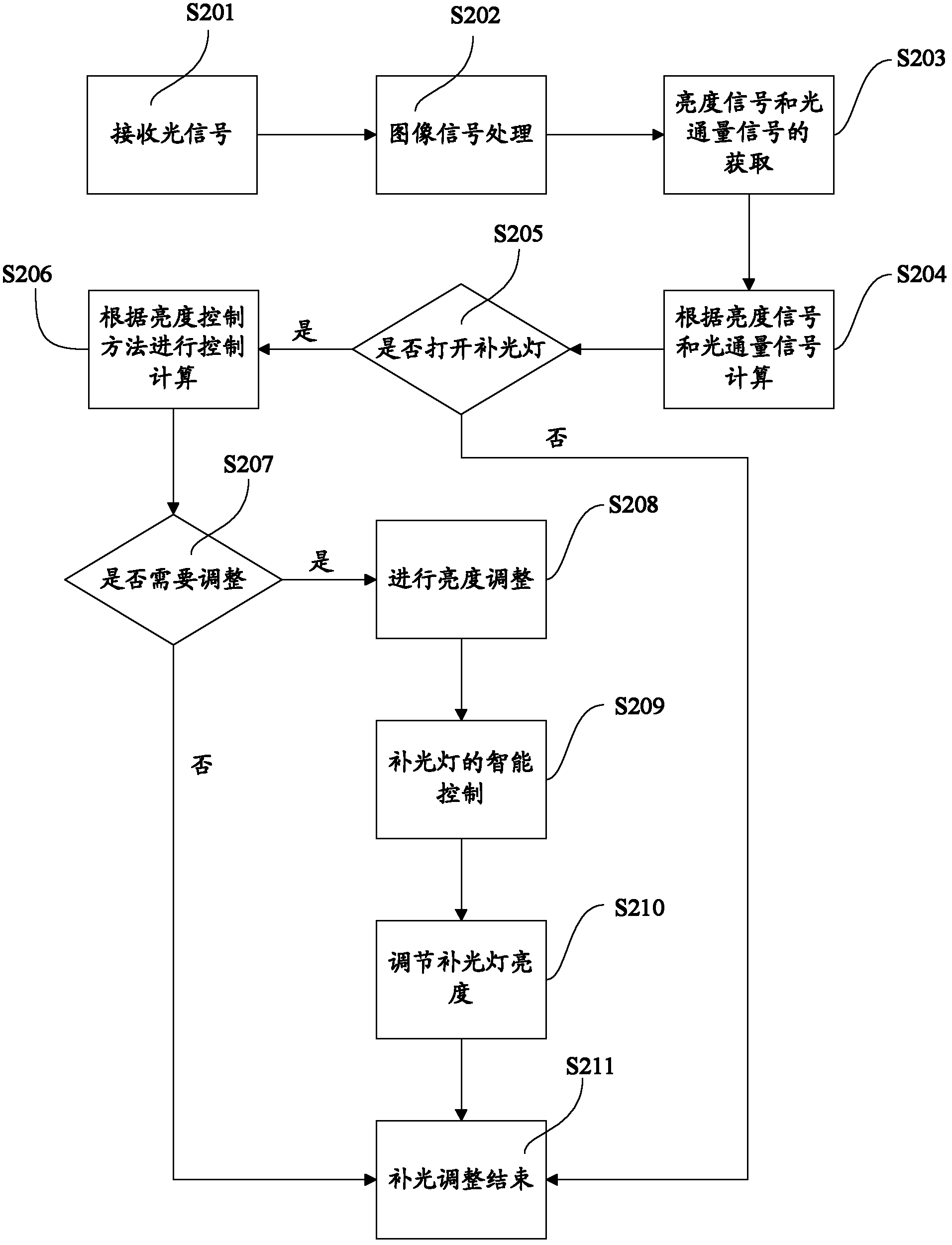
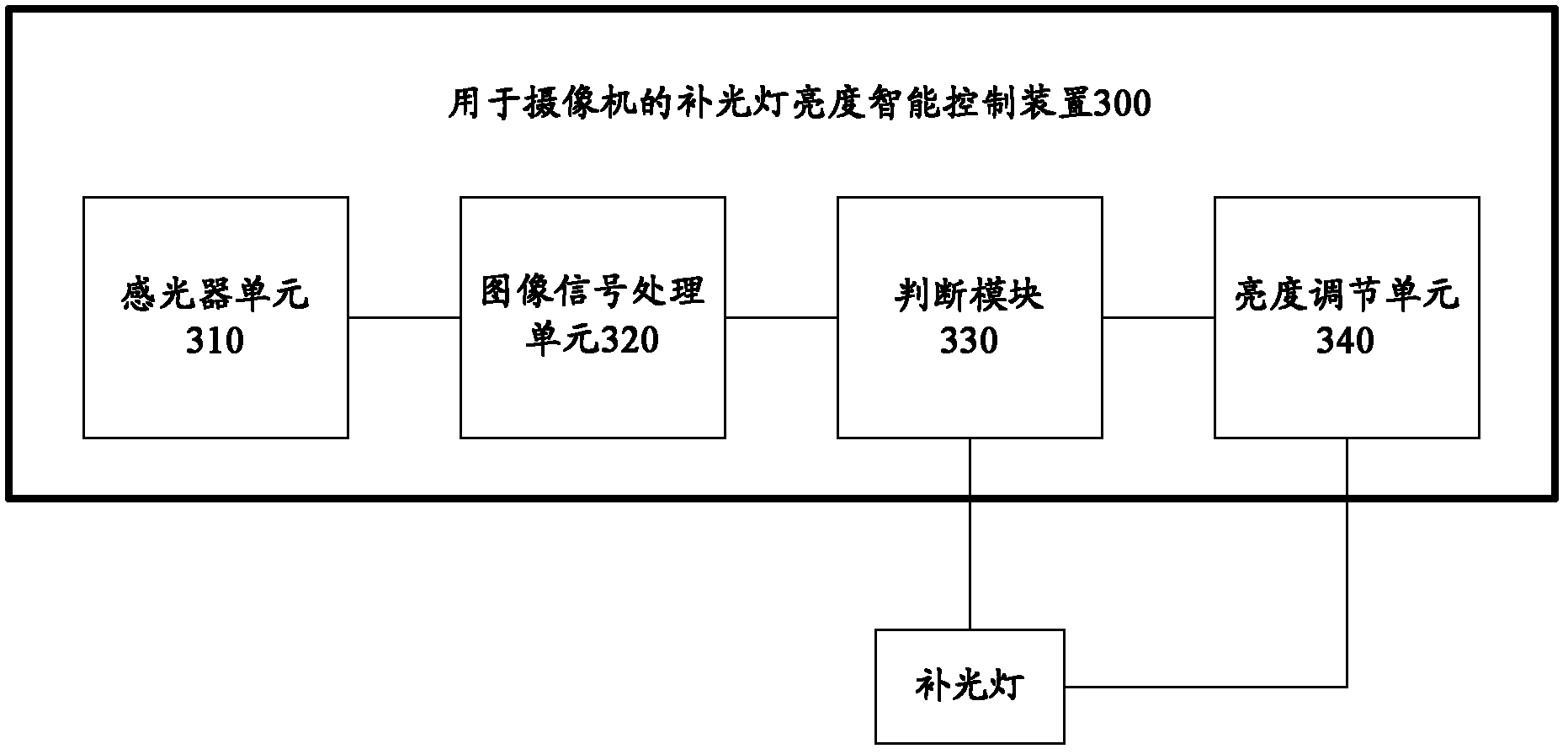
The invention provides a method for intelligently controlling brightness of a flash of a camera. The method comprises the following steps of: receiving an environmental optical signal in an acquisition area of the camera; processing the optical signal to acquire an environmental image in the acquisition area of the camera, and acquiring a brightness signal and a luminous flux signal of the image; determining whether to turn on the flash according to the brightness signal and the luminous flux signal of the image; and comparing the brightness signal with a preset brightness reference value if the flash is turned on, and adjusting a brightness value of the flash according to a comparison result. The invention also provides a device for intelligently controlling brightness of the flash of the camera. The brightness signal is accurately detected, so that the turning-on time of the flash can be accurately and efficiently controlled, and the brightness of the flash is adjusted so as to fulfill the aim of supplementing light; and moreover, the invention has the advantages that: the device is energy-saving, and intensity of the brightness value of the flash is adaptively adjusted.

Description

technical field [0001] The invention relates to the technical field of design of a supplementary light device, in particular to an intelligent control method for brightness of a supplementary light for a camera and an intelligent control device for a supplementary light. Background technique [0002] At present, in a low-light environment, high-definition cameras (non-low-light cameras) cannot effectively image in areas with insufficient light or the image is very noisy and the image quality is poor. Usually, the images captured by high-definition cameras (non-low-light cameras) during the day are high-definition enough, but at night or when there is insufficient light, they cannot achieve the purpose of wide-area exposure, resulting in poor image quality. When) the difference in image quality is very large, which leads to, for example, when the above-mentioned high-definition camera is used in a high-definition surveillance system, the customer is not satisfied with the ima...

Claims


Application Information

Patent Timeline
Patent Type & Authority Applications(China)
IPC IPC(8): H05B37/02G03B15/05
CPCY02B20/48Y02B20/40
Inventor 邓冰蔡建隆何彦兵乔健
Owner CENTRINO BEIJING VIDEO TECH
Learn More