Synchronizing ring assembly and method for forming the friction linings of a synchronizing ring

A technology of synchronous rings and friction plates, which is applied to gear transmission mechanisms, clutches, mechanical drive clutches, etc., and can solve the problems of high manufacturing costs

Inactive Publication Date: 2012-07-11
OTTO FUCHS
View PDF6 Cites 10 Cited by
  • Summary
  • Abstract
  • Description
  • Claims
  • Application Information

AI Technical Summary

Problems solved by technology

The production costs for producing such an intermediate ring with two friction surfaces provided by the friction lining and each assigned to a different friction pair are therefore correspondingly high

Method used


Image

  • Synchronizing ring assembly and method for forming the friction linings of a synchronizing ring
  • Synchronizing ring assembly and method for forming the friction linings of a synchronizing ring
  • Synchronizing ring assembly and method for forming the friction linings of a synchronizing ring

Examples


Embodiment Construction

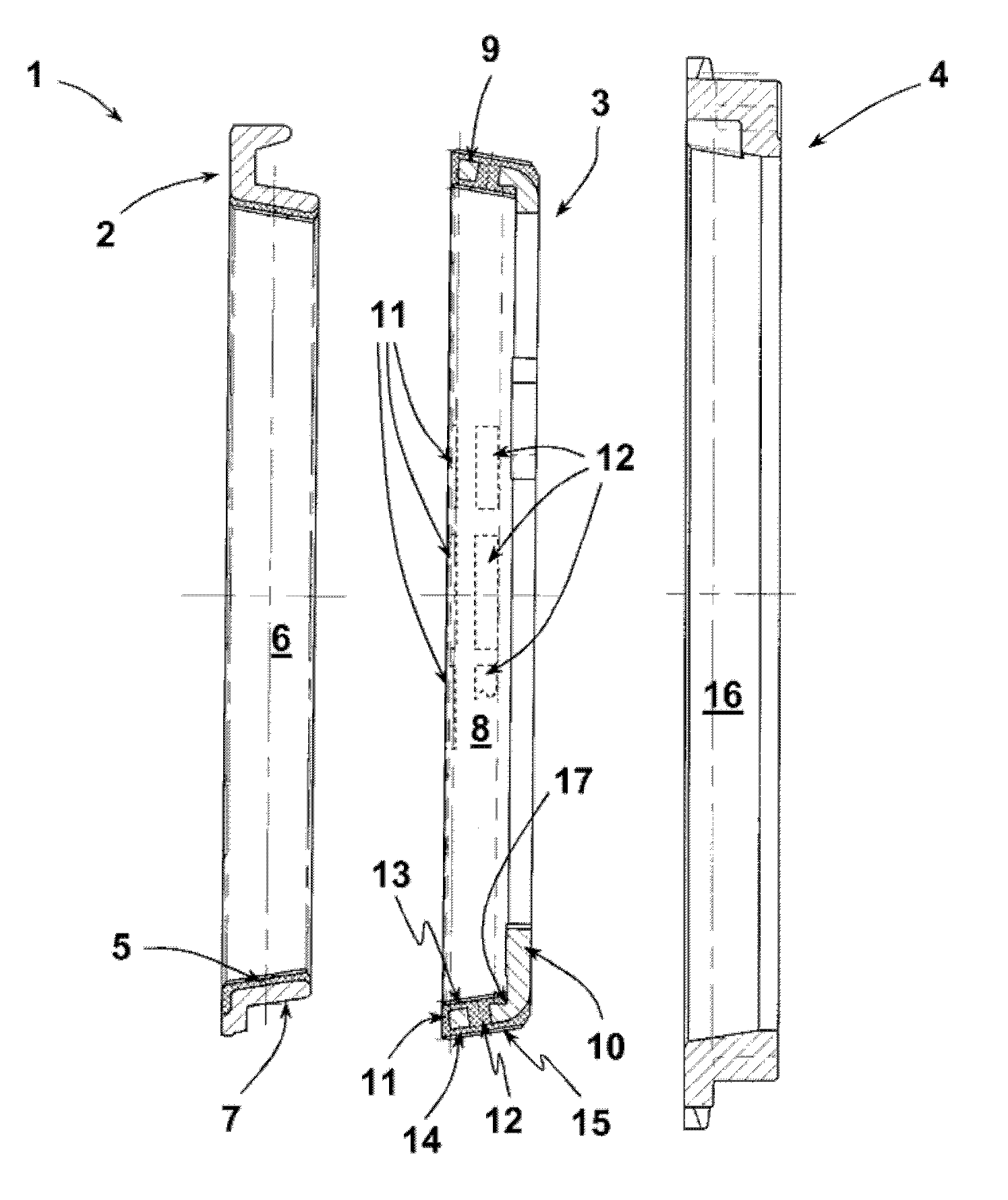
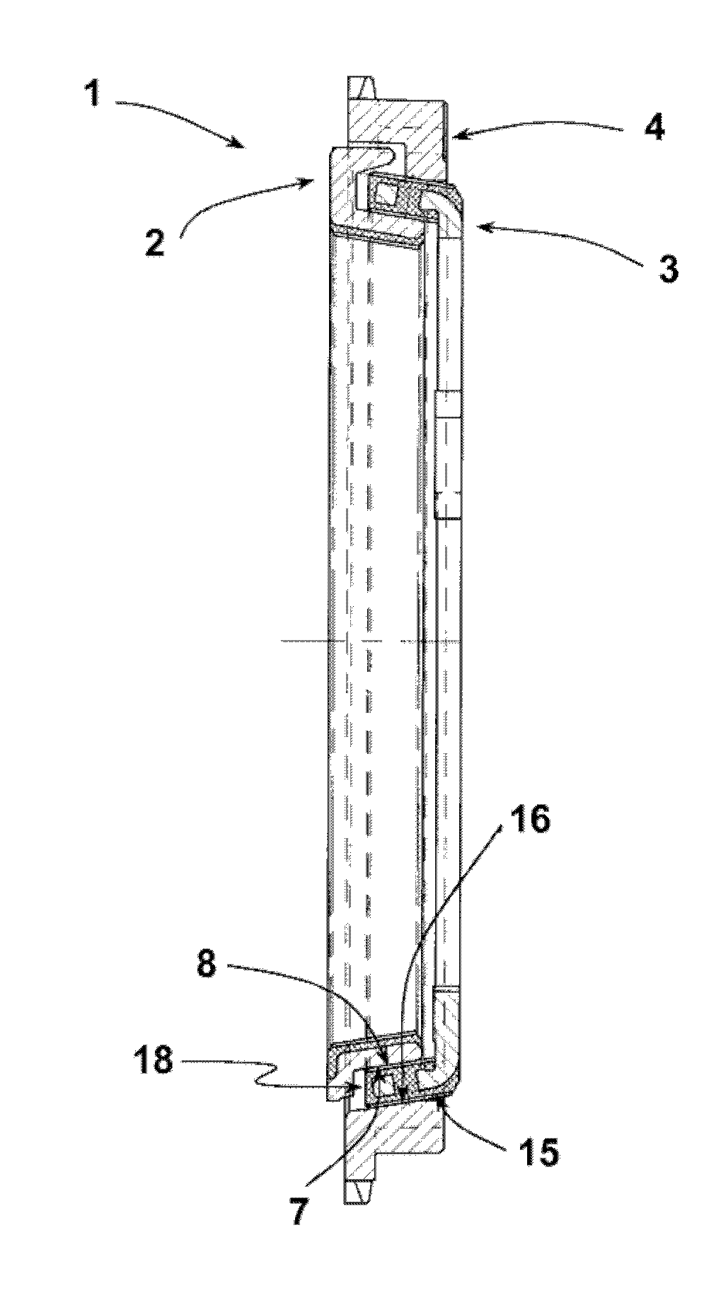
[0017] In the exemplary embodiment shown, the synchronizer ring stack 1 consists of three individual synchronizer rings 2 , 3 , 4 . Synchronizer ring 2 is the inner synchronizer ring. Synchronizing ring 3 is an intermediate ring. The synchronizer ring 4 is the outer synchronizer ring in the synchronizer ring stack 1 . The inner synchronizer ring 2 and the outer synchronizer ring 4 are made of brass material, specifically in the exemplary embodiment shown by a forging process. The inner conical surface 5 of the synchronizing ring 2 is coated with the friction lining 6 by injection molding. In contrast, the outer friction surface 7 of the brass synchronizer ring 2 is not coated. The friction surface 7 forms the friction surface of the first friction pair of the synchronizer ring pack 1 . The friction surface 7 cooperates with the first friction surface 8 of the steel synchronizing ring 3 . Synchronizing ring 3 of steel material is a deep-drawn shaped body made of sheet meta...


PUM


Abstract

A synchronizing ring assembly (1) comprises at least two synchronizing rings (2, 3, 4). The latter each have a frictional surface (7, 8; 15, 16) which can be placed into operative connection to one another to form a friction pairing. At least one of the two synchronizing rings is manufactured from a steel material and the other from a brass material. The brass-material synchronizing ring has a structure in which harder particles P are incorporated into a softer crystalline base material. The frictional surface (8, 15) of the friction pairing of the steel-material synchronizing ring (3), which frictional surface is complementary to the other frictional surface, is formed by a friction lining (13, 14) consisting of an organic binder with filler particles incorporated therein, wherein the filler particles are harder than the binder. A method for forming the friction linings of a synchronizing ring (3) having two friction linings (13, 14) arranged concentrically with respect to each other is defined in that use is made of an injection-mouldable and / or transfer-mouldable plastics compound and the latter is applied by means of a plastics injection-moulding or transfer-moulding method from one side of the ring section (9) which is to be coated, and the friction lining compound is guided through apertures (11, 12) in the ring section (9) from the casting side onto the ring section surfaces which are provided for forming the frictional surfaces (13, 14).

Description

technical field [0001] The invention relates to a synchronizing ring stack, which comprises at least two synchronizing rings, each of which has a friction surface, and the friction surfaces can be mutually connected in order to form a friction pair, wherein at least One of the two synchronizer rings is made of steel, while the other synchronizer ring is made of brass material. Furthermore, the invention relates to a method for forming a friction lining of a synchronizing ring having two friction linings arranged concentrically to one another. Background technique [0002] In a synchronous shift transmission, the shafts which are to be frictionally connected to one another during a gear change are synchronized in their speeds before the frictional engagement is established. For this purpose, the individual gears of such transmissions are synchronized one or more times. Synchronization is established using a sync ring. The synchronizing rings each have a friction surface wh...

Claims


Application Information

Patent Timeline
Patent Type & Authority Applications(China)
IPC IPC(8): F16D23/02
CPCF16D2300/10F16D23/025F16D2250/00F16D2200/0021F16D2200/0026F16D23/02
Inventor J.芒斯特H.格默特H-J.雷克特恩
Owner OTTO FUCHS
Why Eureka
Try Eureka