breech devices for hand-held firearms

A breech and firearm technology, applied in the breech mechanism, weapon accessories, firing/trigger mechanism, etc., to achieve the effect of simple structure and functional safety

Active Publication Date: 2014-10-15
弗拉迪米尔·劳甘库克
View PDF8 Cites 0 Cited by
  • Summary
  • Abstract
  • Description
  • Claims
  • Application Information

AI Technical Summary

Problems solved by technology

[0007] Another disadvantage of this device is that the locking device is located in the carrier of the breech block

Method used


Image

  • breech devices for hand-held firearms
  • breech devices for hand-held firearms
  • breech devices for hand-held firearms

Examples


Embodiment Construction

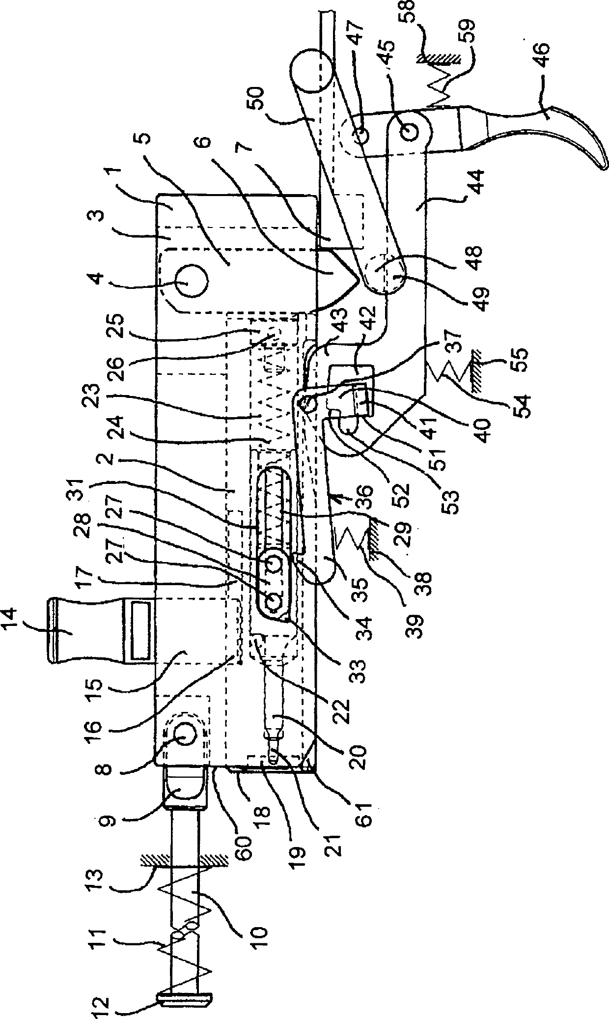
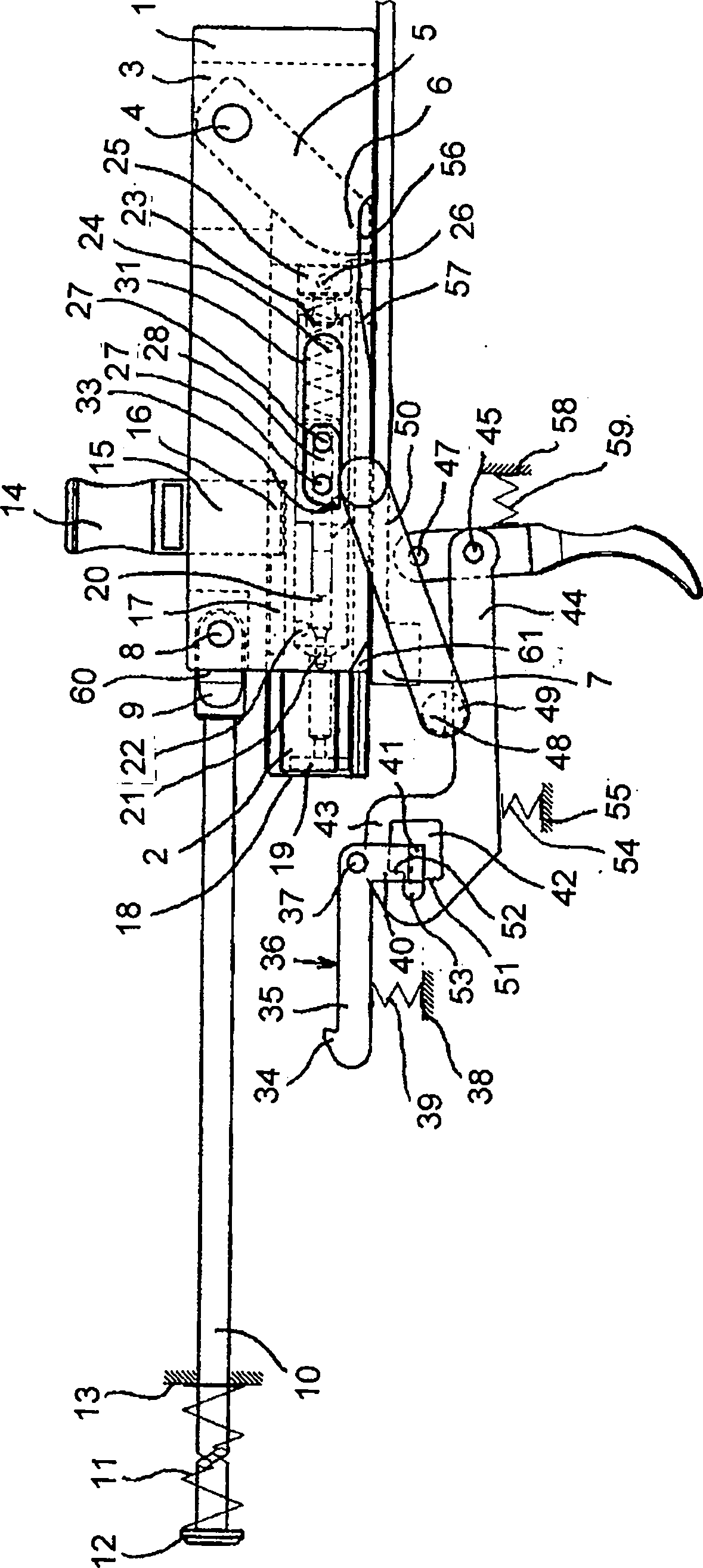
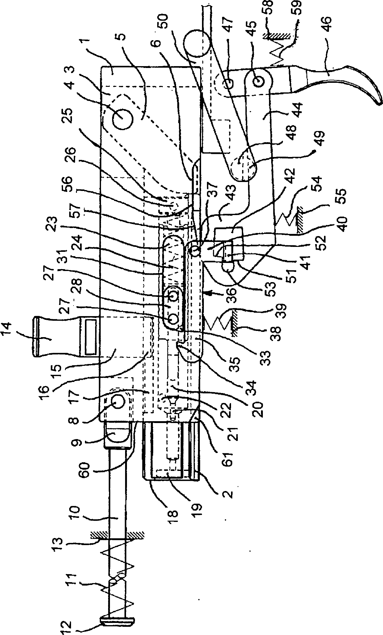
[0039] The breech device according to the invention comprises a carrier 1 slidably arranged in the housing and a breech block 2 slidably arranged in the carrier 1 . The rear part of the carrier 1 is at least partly open in the vertical direction, advantageously in the form of a well 3, inside the well 3 the locking arm 5 pivots on the support pin 4, and the free end 6 of the locking arm 5 is designed To engage with the lateral stop 7, which is a non-movable part of the firearm casing. At the front part of the carrier 1, the end 9 of the guide rod 10 is hinged on the fixed pin 8, the forward spring 11 is sleeved on the guide rod 10, and one end of the forward spring 11 is fixed at one end of the guide rod 10 by a The collar 12 bears and the other end of the forward spring 11 bears at a bearing area 13 of the firearm housing (not shown). The tensioning pin 15 is provided with a grip 14 and is vertically anchored in the carrier 1 , the end 16 of the tensioning pin 15 extending i...


PUM


Abstract

A breech assembly for a hand firearm includes a firearm housing, a trigger mechanism, a carrier slidably disposed within the firearm housing, and a breech block engaged with the carrier and having a striker. The breech device also includes a tensioning element slidably engaged with the carrier and coupled to at least one follower pin engaged with the striker and slidably coupled with the breech block. The tensioning element includes a protrusion having a forwardly directed nose adapted to engage a detent on the trigger mechanism. The breech assembly also includes a tension pin slidably engaged with the carrier and the breech block.

Description

Background technique [0001] The invention relates to a breech device for a hand-held firearm, comprising a firearm casing, the firearm casing includes a slidingly arranged carrier, the carrier has a breech block, the breech device includes a slidingly arranged firing pin, the firing pin has a striker, and the locking arm is on the bearing Pivot in the rear of the piece. [0002] Patent documents CZ 58598 and CZ 59377 (Fransek Janecek et al.) describe a locking mechanism in which the locking mechanism functions from a so-called rear position, which means that the entire breech device is in the rear position before firing. In this mechanism, the striker is fixed to the carrier of the breech block and fired only after full locking. This configuration of the entire locking mechanism is not preferred because if the firearm is ready to fire, the breech mechanism must be unlocked and the return spring must be fully tensioned. Due to the effect of the large mass of the breech device...

Claims


Application Information

Patent Timeline
Patent Type & Authority Patents(China)
IPC IPC(8): F41A19/10F41A19/13F41A3/64
CPCF41A19/33F41A5/02F41A19/32F41A3/38
Inventor 弗拉迪米尔·劳甘库克
Owner 弗拉迪米尔·劳甘库克
Why Eureka
Try Eureka