Zoom lens system, image-capturing device, and camera
A zoom lens and lens technology, applied in the field of cameras, can solve the problems of inability to shorten the total length of the lens, the total length of the lens, and the number of lenses, and achieve the effect of the total length of the lens, the number of lenses, and the high resolution.
- Summary
- Abstract
- Description
- Claims
- Application Information
AI Technical Summary
Problems solved by technology
Method used
Image

Examples
Embodiment approach 1~6
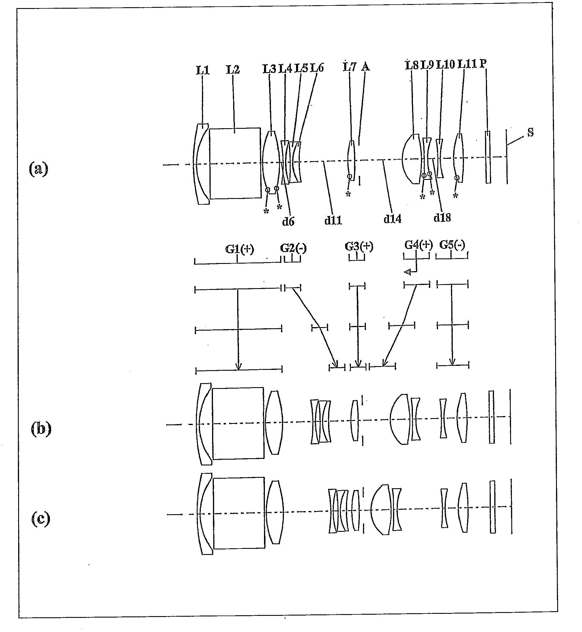
[0116] figure 1 , 4 , 7, 10, 13, and 16 are lens arrangement diagrams of the zoom lens systems according to Embodiments 1 to 6.
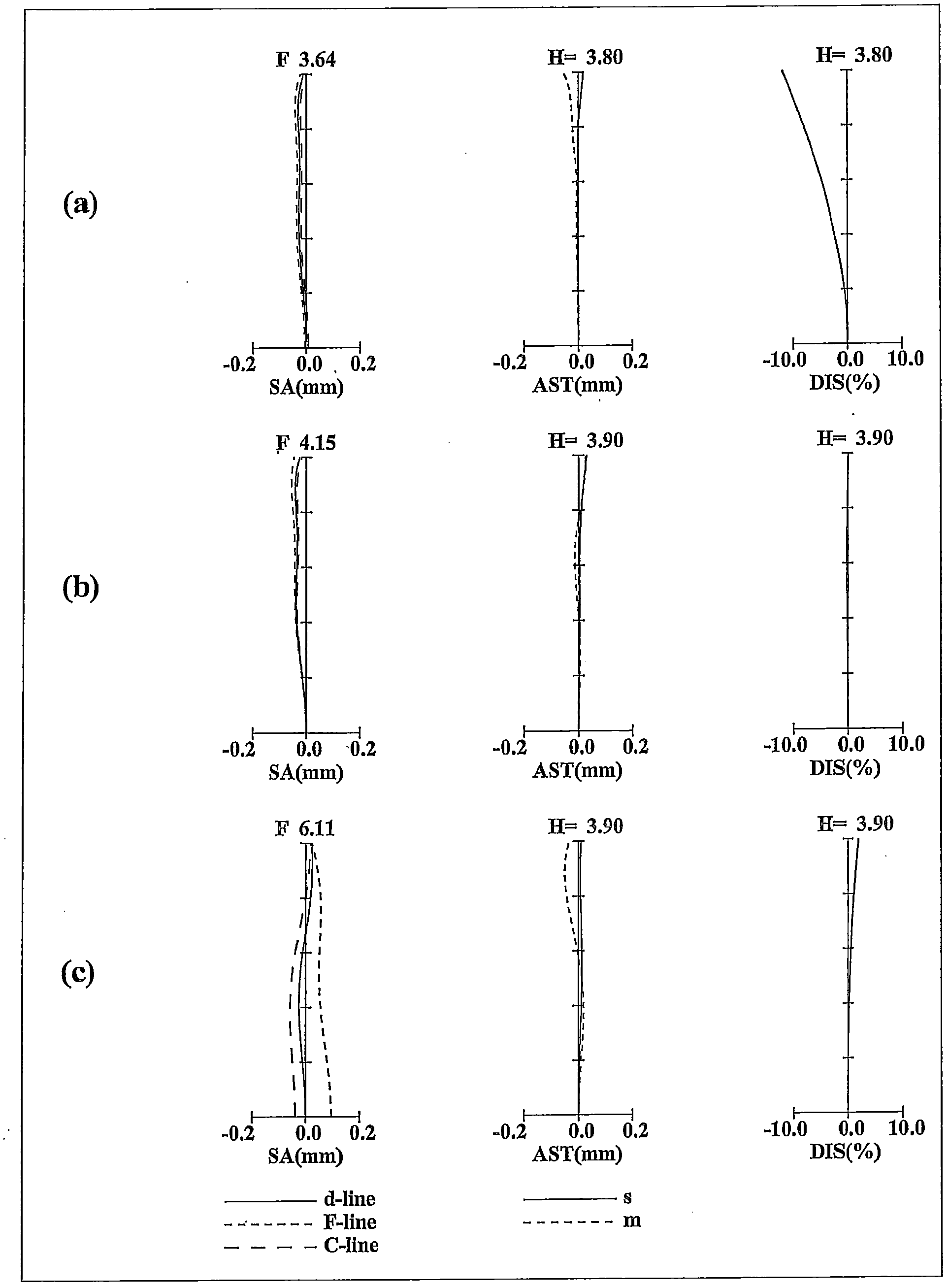
[0117] figure 1 , 4, 7, 10, 13 and 16 all represent the zoom lens system in the infinity focus state. In each figure, the figure (a) shows the wide-angle end (the shortest focal length state: focal length f W ) of the lens structure, (b) diagram represents the intermediate position (intermediate focal length state: focal length ), and (c) shows the telephoto end (longest focal length state: focal length f T ) of the lens structure. In addition, in each figure, the broken line arrows provided between (a) and (b) are obtained by sequentially connecting the positions of the lens groups in each state of the wide-angle end, the intermediate position, and the telephoto end from top to bottom. the straight line. Therefore, the wide-angle end and the middle position and the middle position and the telephoto end are simply connected by a straight li...
Embodiment approach 7
[0226] Figure 19 It is a schematic block diagram of the digital still camera which concerns on Embodiment 7. Figure 19 Among them, the digital still camera includes an imaging device including a zoom lens system 1 and an imaging element 2 of a CCD, a liquid crystal display 3 , and a casing 4 . As the zoom lens system 1, the zoom lens system according to Embodiment 1 is used. Figure 19 Among them, the zoom lens system 1 includes a first lens group G1, a second lens group G2, a third lens group G3, an aperture stop A, a fourth lens group G4, and a fifth lens group G5. The zoom lens system 1 is arranged on the front side of the casing 4 , and the imaging element 2 is arranged on the rear side of the zoom lens system 1 . The liquid crystal display 3 is arranged on the rear side of the casing 4 , and the optical image of the subject formed by the zoom lens system 1 is formed on the image plane S. As shown in FIG.
[0227] As described above, by using the zoom lens system acco...
Embodiment 1
[0242] The zoom lens system of Numerical Example 1 and figure 1 The illustrated embodiment 1 corresponds. Table 1 shows surface data of the zoom lens system of Numerical Example 1; Table 2 shows aspheric surface data; and Table 3 shows various data.
[0243] surface data
[0244]
[0245]
[0246] Table 2 (aspheric data)
[0247] side 5
[0248] K=0.00000E+00, A4=-9.10248E-05, A6=3.01897E-06, A8=-2.03901E-07A10=5.12339E-09, A12=0.00000E+00
[0249] side 6
[0250] K=0.00000E+00, A4=2.99214E-05, A6=2.73934E-06, A8=-1.72113E-07A10=4.79494E-09, A12=0.00000E+00
[0251] side 12
[0252] K=-8.66353E-01, A4=1.11174E-05, A6=-3.55647E-05, A8=7.95030E-06A10=-8.26197E-07, A12=3.09544E-08
[0253] side 17
[0254] K=0.00000E+00, A4=-1.94974E-03, A6=1.32414E-04, A8=-1.10073E-05A10=3.18781E-07, A12=0.00000E+00
[0255] side 18
[0256] K=0.00000E+00, A4=-1.14750E-04, A6=2.31259E-04, A8=-1.31423E-05A10=6.93486E-07, A12=0.00000E+00
[0257] side 21
[0258] K=0.00000E+00, A...
PUM
 Abstract
Description
Claims
Application Information
 - R&D
- Intellectual Property
- Life Sciences
- Materials
- Tech Scout
- Unparalleled Data Quality
- Higher Quality Content
- 60% Fewer Hallucinations
Browse by: Latest US Patents, China's latest patents, Technical Efficacy Thesaurus, Application Domain, Technology Topic, Popular Technical Reports.
© 2025 PatSnap. All rights reserved.Legal|Privacy policy|Modern Slavery Act Transparency Statement|Sitemap|About US| Contact US: help@patsnap.com