Transfer cart with crankshafts

A turnover car and crankshaft technology, which is applied to multi-axis trolleys, trolleys, motor vehicles, etc., can solve the problems of waste of handling time, low turnover efficiency, and increased handling costs, and achieve reasonable structure, low handling costs and wide applicability Effect

Inactive Publication Date: 2012-07-18
TIANRUN IND TECH CO LTD
View PDF3 Cites 7 Cited by
  • Summary
  • Abstract
  • Description
  • Claims
  • Application Information

AI Technical Summary

Problems solved by technology

In this way, the handling time is wasted, the handling cost is also increased, and the turnover efficiency is low

Method used


Image

  • Transfer cart with crankshafts
  • Transfer cart with crankshafts
  • Transfer cart with crankshafts

Examples


Embodiment Construction

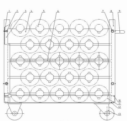
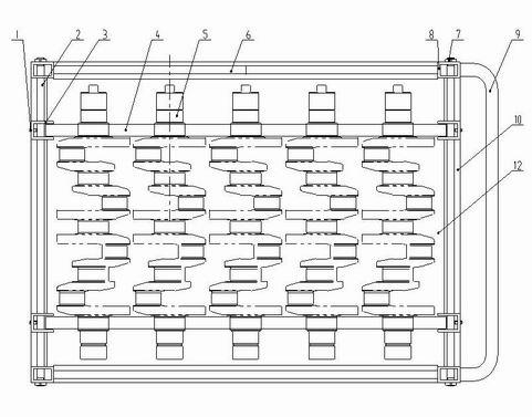
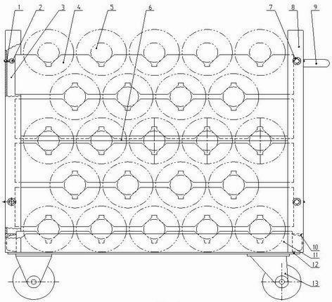
[0017] From figure 1 , figure 2 As can be seen in the figure, a crankshaft turnover vehicle is provided with a base plate 12 and a wheel set 13, and the four corners below the base plate 12 are welded and fixed to the upper plane of the wheel set 13. The specific composition and structure of the wheel set 13 belongs to the prior art and will not be repeated. .

[0018] Four uprights 8 are vertically welded on the four corners of the bottom plate 12 of the present invention, including two front uprights and two rear uprights. Around the outer surface of the lower end of the column 8 and around the base plate 12 , a frame 10 is welded on the base plate 12 . Column 8 is processed by square steel pipe, and frame 10 is processed by channel steel. Between the two front columns and between the two rear columns, two horizontally arranged guide connecting rods 2 are respectively arranged up and down, and an intermediate connecting rod 6 is arranged between the front and rear column...


PUM


Abstract

The invention relates to a transfer cart with crankshafts, which is provided with a bottom plate and wheel sets. Four vertical columns and a frame are welded on the bottom plate, two guide connecting rods are respectively arranged between the two front vertical columns and between the two rear vertical columns, the two guide connecting rods on the front side and the two guide connecting rods on the rear side are perpendicularly connected with two limit groove plates respectively, and a bottom bearing plate and a plurality of middle bearing partitions are sequentially mounted between the frontlimit groove plate and the rear groove plate layer by layer. V-shaped grooves of the upper end face of the lower middle bearing partition are arranged oppositely to V-shaped grooves of the lower end face of the upper middle bearing partition, and V-shaped grooves of the lower end face and V-shaped grooves of the upper end face of the same middle bearing partition are arranged at intervals in a staggered manner. When in use, the crankshafts and the middle bearing partitions are sequentially mounted layer by layer, the crankshafts in layers are disposed in a staggered manner so that space can be utilized sufficiently and more crankshafts can be disposed. The transfer cart with the crankshafts is reasonable in structure, simple in operation, high in transferring efficiency, low in transferring cost and wide in application.

Description

technical field [0001] The invention relates to a transport turnover tool between crankshaft processing procedures, in particular to a crankshaft turnover vehicle. Background technique [0002] We know that when crankshafts are produced in batches with multiple varieties, for special processes, it is often necessary to concentrate separate equipment for processing, usually with a turnover vehicle, which requires the turnover vehicle to be loaded as much as possible within a limited space. Most of the crankshafts loaded on the crankshaft turnover car are arranged in a single layer; there are also individual ones arranged in multiple layers, which place the crankshafts side by side in a row, and the number of crankshafts loaded in a limited space is small. Like this, the handling time is wasted, the handling cost is also increased, and the turnover efficiency is low. Contents of the invention [0003] The technical problem to be solved by the present invention is to overcom...

Claims


Application Information

Patent Timeline
Patent Type & Authority Applications(China)
IPC IPC(8): B62B3/10
Inventor 丛建臣宋文友马明亮张亚王旭阳
Owner TIANRUN IND TECH CO LTD
Why Eureka
Try Eureka