Electromagnetic type underwater sensor network node carrying device

A technology of underwater sensors and network nodes, applied in network topology, underwater operation equipment, electrical components, etc., can solve the problems of unsuitable daily monitoring of hydrological and marine environments, difficulties in collecting data and updating and maintaining equipment, and limited energy of underwater sensor networks and other issues, to achieve the effect of strong practicability, long service life and low cost

Inactive Publication Date: 2012-07-18
QINGDAO UNIV OF SCI & TECH
View PDF7 Cites 12 Cited by
  • Summary
  • Abstract
  • Description
  • Claims
  • Application Information

AI Technical Summary

Problems solved by technology

With the increasing demand for marine monitoring, various carrying devices have emerged as the times require. At this stage, the main means used in marine monitoring are buoy systems and submersible buoy systems. Both types of systems involve the carrying of underwater monitoring equipment. Among them, the underwater sensor network based on the buoy system is often only used for sea surface monitoring and does not involve underwater applications; while the underwater sensor network based on the submersible buoy system is difficult to collect data collected by the system and update and maintain equipment. In addition, these Most of the systems are complex in technology, difficult to design and manufacture, high in cost, and complicated in installation steps. They are not suitable for daily monitoring of the hydrological and marine environment. In addition, the energy of the underwater sensor network is limited. Problems to be considered in the design of network node carrying equipment

Method used


Image

  • Electromagnetic type underwater sensor network node carrying device
  • Electromagnetic type underwater sensor network node carrying device
  • Electromagnetic type underwater sensor network node carrying device

Examples


Embodiment Construction

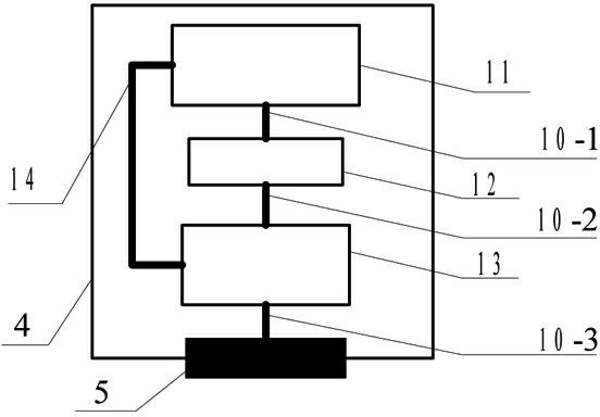
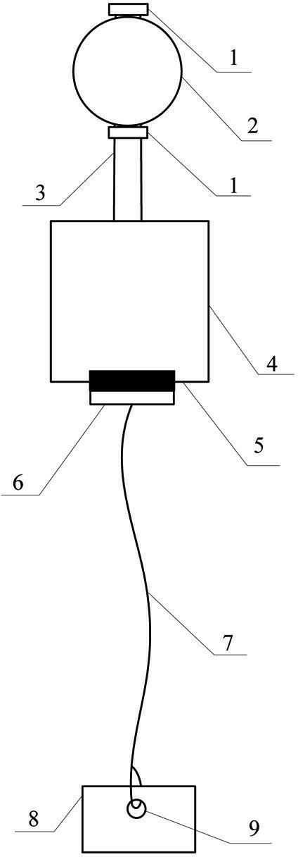
[0016] Such as figure 1 , 2 The shown electromagnetic underwater sensor network node carrying device includes a buoyancy component, an underwater perception control component, and an anchor component. The upper end of the support pipe 3 is fixed with a fixing bolt 2; the underwater sensing control assembly includes a sealed cabin 4 and an underwater sensor network node 11 placed in the sealed cabin 4, an electromagnetic control circuit 13, a power supply circuit 12, a data line 14 and The electromagnet plate 5 fixed on the lower surface of the airtight cabin 4; the underwater sensor network node 11, the power supply circuit 12 and the electromagnetic control circuit 13 are respectively fixed at the upper, middle and lower positions of the airtight cabin 4; the data line 14 connects the underwater sensor network node 11 and the electromagnetic control circuit 13; the power supply circuit 12 supplies power to the underwater sensor network node 11 and the electromagnetic control...


PUM


Abstract

The invention discloses an electromagnetic type underwater sensor network node carrying device, which comprises a buoyancy assembly, an underwater sensing control assembly and an anchoring assembly. The underwater sensing control assembly comprises a sealed cabin, a underwater sensor network node placed in the sealed cabin, an electromagnetic control circuit, a power circuit, a data line and an electromagnetic iron plate fixed on the lower surface of the sealed cabin, the underwater sensor network node, the power circuit and the electromagnetic control circuit are respectively fixed on the upper portion, the middle portion and the lower portion of the sealed cabin, and the data line is connected with the underwater sensor network node and the electromagnetic control circuit. The buoyancy assembly is connected with the underwater sensing control assembly and located on the top portion of the whole device, and the anchoring assembly is located on the lower portion of the device. The electromagnetic type underwater sensor network node carrying device needs no manual intervention, and is simple in updating maintenance, convenient in operation, low in cost, strong in practical applicability, good in stability, long in service life and applicable to underwater tests and marine monitoring under various situations.

Description

technical field [0001] The invention relates to an underwater carrying device, in particular to an electromagnetic underwater sensor network node carrying device. Background technique [0002] The ocean plays an increasingly significant role in human life. The underwater sensor network has been widely used in the ocean monitoring system due to its advantages of convenient deployment and flexible networking, and has attracted more and more attention. Underwater sensor network node carrying technology is a new underwater monitoring technology developed on the basis of traditional technology along with the development of marine science. The underwater sensor network node carrying device is a modern ocean observation facility, which assists the underwater sensor network node to collect marine environmental data stably and reliably. With the increasing demand for marine monitoring, various carrying devices have emerged as the times require. At present, the main means used in mar...

Claims


Application Information

Patent Timeline
Patent Type & Authority Applications(China)
IPC IPC(8): B63C11/52H04W84/18
Inventor 郭瑛刘聿涛
Owner QINGDAO UNIV OF SCI & TECH
Why Eureka
Try Eureka