
Multifunctional efficient contact reactor

A reactor and multi-functional technology, applied in the direction of flocculation/sedimentation water/sewage treatment, etc., can solve the problems of high shear force and shear rate, affecting the effect of sedimentation treatment, and power consumption of the agitator, so as to save energy and improve The effect of the mixed reaction effect

Active Publication Date: 2012-07-18
CHINA MACHINERY INT ENG DESIGN & RES INST
View PDF5 Cites 6 Cited by
  • Summary
  • Abstract
  • Description
  • Claims
  • Application Information

AI Technical Summary

Problems solved by technology

[0003] Publication No. CN102068955A and Application No. 201010589358.4 disclose a "flocculation reactor with special-shaped spoiler", the structure of which includes a shell, an agitator placed in the middle of the shell, and a special-shaped spoiler arranged on the inner wall of the shell. The baffle plate and the spoiler bar arranged on the upper head, the upper part of the shell has a feed port, and the bottom has a discharge port; the "flocculation reactor with a special-shaped spoiler" through different forms The agitator cooperates to fully mix the flocculant with the liquid, increase the micro-vortex, and achieve a good flocculation effect, but because the flocculation reactor uses the stirring process to realize the mixed reaction of pollutants and flocculant or other agents, during operation, its shear The shear force and shear rate are large, and the flocs are easily broken, which affects the effect of subsequent sedimentation treatment, and the agitator needs to consume electric energy

Method used


Image

  • Multifunctional efficient contact reactor
  • Multifunctional efficient contact reactor
  • Multifunctional efficient contact reactor

Examples


Embodiment Construction

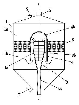
[0026] See attached picture. The present invention comprises a housing 1 with an inner cavity, the upper part of the housing 1 has a water outlet 2, and the inner cavity of the housing 1 is provided with a reaction device 3 communicated with a water inlet pipe and a distributing cylinder 4 with an open lower part;

[0027] The main body of the housing 1 is a cylindrical structure, and the upper and lower ends are conical structures;

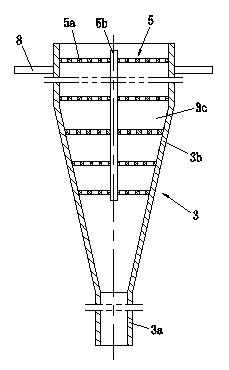
[0028] The reaction device 3 includes a water inlet pipe section 3a and a reactor body 3b connected to the water inlet pipe section. The reactor body 3b has an inner chamber 3c, and the upper part has an outlet. The upper part of the reactor body 3b is located in the distribution cylinder 4, There is a backflow passage 4a for water flow between the reactor body 3 and the cylinder wall of the distribution cylinder 4, and the outlet on the upper part of the reactor body 3b communicates with the backflow passage 4a and the opening at the bottom of t...


PUM


Abstract

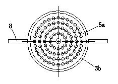
The invention relates to a multifunctional efficient contact reactor and belongs to a device for water treatment. The upper part of a casing (1) is provided with a water outlet (2), a casing inner cavity is provided with a distribution tube body (4) and a reaction device (3) communicated with a water inlet pipe, the reaction device (3) is provided with a water inlet pipe section (3a) and a reactor body (3b) positioned in the distribution tube body (4), a back flow passage (4a) is arranged between the reactor body and the distribution tube body, an outlet arranged at the upper part of the reactor body is communicated with the flow back passage (4a) and an open opening arranged at the lower part of the distribution tube body (4), a combined component (5) consisting of a plurality of layers of hole plates (5a) is arranged in a reactor body inner cavity (3c), the outer side of the distribution tube body (4) is provided with a filling layer (6), an upper cavity (1a) of the casing is communicated with the water outlet (2), a lower cavity (1b) is communicated with the open opening arranged at the lower part of the distribution tube body (4), and a mud discharge opening (7) is arranged onthe lower wall of the lower cavity (1b). The flocculation or mixing effect can be effectively improved, and the multifunctional efficient contact reactor has the characteristic that multiple functions are realized by one machine.

Description

technical field [0001] The invention relates to a contact reactor in the water treatment process, specifically a contact flocculation reactor that can be used in the flocculation stage of the water supply treatment system, the urban sewage advanced treatment system and the industrial wastewater treatment system, or the contact flocculation reactor in other chemical reaction stages such as advanced oxidation. mixing reactor. Background technique [0002] In the water treatment system, contact flocculation reaction (hereinafter referred to as "flocculation reaction") or contact mixing reaction (hereinafter referred to as "mixed reaction") is an important link in the process of water purification. Flocculation reaction refers to the destabilization of solid particles, colloidal particles and macromolecular substances in the water body under the action of flocculants, and then under the action of macroscopic or microscopic forces, they contact and collide with each other, result...

Claims


Application Information

Patent Timeline
Patent Type & Authority Applications(China)
IPC IPC(8): C02F1/52
Inventor 蒋剑虹罗松柏罗友元吴玉华谢立祥黄子平尹疆
Owner CHINA MACHINERY INT ENG DESIGN & RES INST
Learn More