

High-temperature high-frequency in-situ test device for material mechanical property
An in-situ testing, high-frequency material technology, applied in measuring devices, analyzing materials, testing the strength of materials by applying stable tension/pressure, etc. The effect of combined installation of the whole machine, compact layout and simple structure
Pending Publication Date: 2018-04-20
JILIN UNIV
View PDF2 Cites 15 Cited by
- Summary
- Abstract
- Description
- Claims
- Application Information
AI Technical Summary
Problems solved by technology
[0006] The purpose of the present invention is to provide an in-situ test device for the mechanical properties of high-temperature and high-frequency materials, which solves the problem that the existing technology c
Method used
View moreImage
Smart ImageViewing Examples

Examples
 PUM
 Abstract
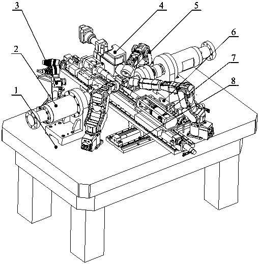
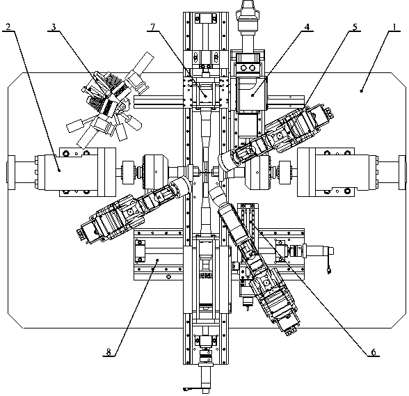
The invention relates to an in-situ test device for mechanical properties of high-temperature and high-frequency materials, which belongs to the technical field of material testing machines and precision instruments. It mainly consists of static tension/compression-low cycle fatigue loading module, in-situ monitoring module, temperature loading and monitoring module, static bending loading module, ultrasonic fatigue loading module and position switching mechanism of ultrasonic fatigue and static bending loading module. In the present invention, components such as transducers, horns and probes are used to realize high-frequency loading on the test piece, high-frequency servo hydraulic cylinder components are used to load tension/compression loads and low-frequency alternating loads, and halogen heating lamps are used to apply high temperature Load, and measure the strain of the specimen in real time through the non-contact measurement method through the in-situ monitoring module. The invention has a simple structure and a compact layout, can realize composite loading of bending ultrasonic fatigue and tensile load, and can be coupled with the temperature field, and can more realistically simulate complex working conditions of materials in service in key fields such as aviation and aerospace under the action of high-temperature and high-frequency alternating loads. condition.
Description
technical field [0001] The invention relates to the field of precision sensors and precision instruments, in particular to an in-situ test device for mechanical properties of high-temperature and high-frequency materials. It can realize the application of "tensile-bending" composite load and low-frequency alternating load on the specimen, and can also realize asymmetric tension-compression ultrasonic fatigue loading and composite loading of bending ultrasonic fatigue and tensile load, and can be coupled with the temperature field Loading can more realistically simulate the complex working conditions of materials in service in key fields such as aviation, aerospace and nuclear industries under high temperature and high frequency alternating loads. It adopts modular design and integrates an automatically controllable temperature loading and monitoring module. Combined with the in-situ monitoring module, it can further study the deformation and damage mechanism, microstructure ch...
Claims
Login to View More Application Information
Patent Timeline
 IPC IPC(8): G01N3/18G01N3/60
CPCG01N3/18G01N3/60G01N2203/0073G01N2203/0641
Inventor赵宏伟王赵鑫万杰赵久成薛博然李文博王吉如徐博文王军炎刘思含
OwnerJILIN UNIV