
Urban road water permeability cement concrete pavement structure and construction process thereof

A cement concrete and water permeability technology, which is applied to the coagulation pavement, roads, roads and other directions of on-site paving, can solve the problems of climate deterioration, high temperature, heat island effect, etc., and achieve reasonable structural design, convenient construction, and enhanced water permeability. Effect

Active Publication Date: 2012-07-18
CHANGAN UNIV
View PDF5 Cites 21 Cited by
  • Summary
  • Abstract
  • Description
  • Claims
  • Application Information

AI Technical Summary

Problems solved by technology

[0003] First, the amount of rainwater that can infiltrate into the ground has decreased significantly, while industrial production and modern life have doubled the amount of groundwater extracted, resulting in a sharp drop in the groundwater level, insufficient water in the soil, lack of oxygen, and rising ground temperature, etc., thus directly affecting the environment. The health of urban vegetation further exacerbates the problem of drought and water shortage in the city
[0004] Second, impermeable pavement is difficult to exchange heat and humidity with the air, which is prone to produce the "heat island effect", which makes the temperature inside the city too high, leading to climate deterioration;
[0005] Third, when there is concentrated rainfall in a short period of time, a large amount of rainwater can only be discharged into the river through underground drainage facilities, which greatly increases the burden on the drainage facilities, and the roads are prone to water accumulation, which brings a negative impact on the comfort and safety of vehicles and pedestrians. Negative Effects

Method used


Image

  • Urban road water permeability cement concrete pavement structure and construction process thereof
  • Urban road water permeability cement concrete pavement structure and construction process thereof
  • Urban road water permeability cement concrete pavement structure and construction process thereof

Examples


Embodiment Construction

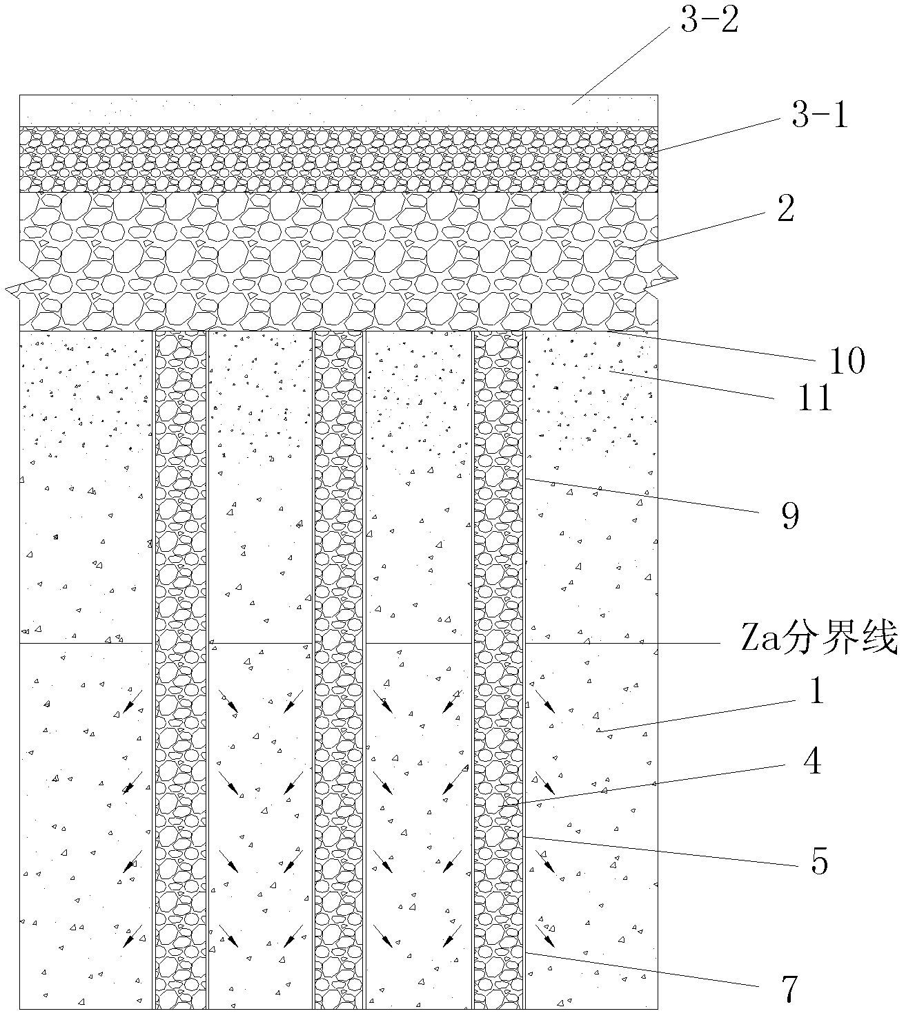
[0049] like figure 1 A permeable cement concrete pavement structure for an urban road as shown, comprising an asphalt-stabilized drainage base 2 paved on the roadbed and paved with asphalt-stabilized crushed stones, and a road surface layer paved on the asphalt-stabilized drainage base 2 . The road surface layer is a road surface layer 1 or a road surface layer 2 consisting of a lower layer 3-1 and an upper layer 3-2 paved on the lower layer 3-1, and the road surface layer 1 is a large gap. Graded drainage asphalt wear layer or porous cement concrete pavement pavement layer paved with porous cement concrete pavement material, the upper layer 3-2 is paved with porous cement concrete pavement material or is open graded with large voids A drainage-type asphalt wear layer is provided, and the lower layer 3-1 is a large-void open-graded drainage-type asphalt wear layer. A plurality of water-permeable piles with the same structure and size are arranged inside the roadbed, and a pl...


PUM

PropertyMeasurementUnit
Wet densityaaaaaaaaaa
Layer thicknessaaaaaaaaaa

Abstract

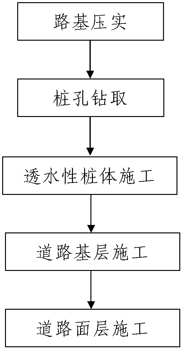
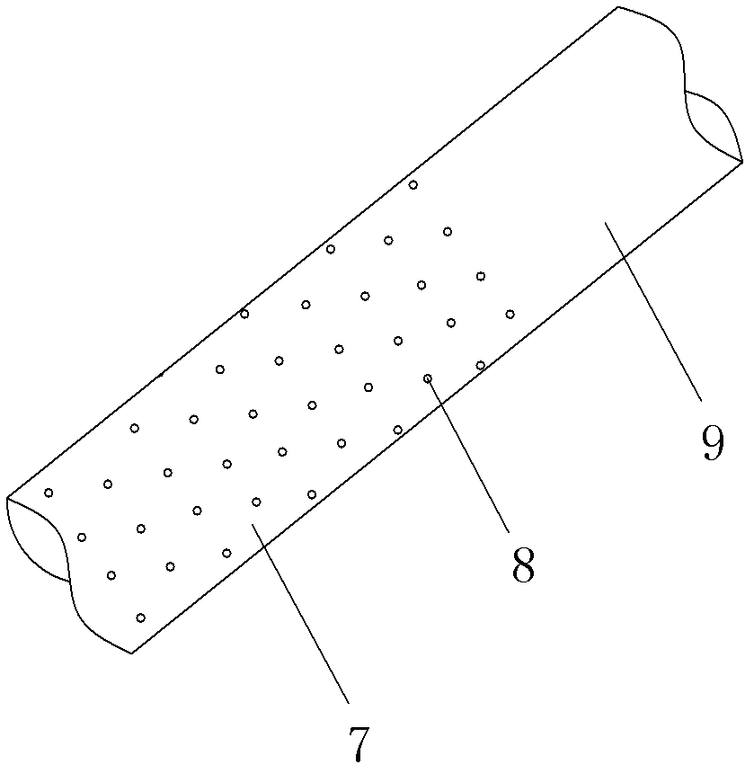
The invention discloses an urban road water permeability cement concrete pavement structure and a construction process thereof. The pavement structure comprises an asphalt stable water draining base layer paved on a roadbed and a road surface layer paved on the asphalt stable water draining base layer, wherein the road surface layer is a first road surface layer or a second road surface layer composed of a lower surface layer and an upper surface layer paved on the lower surface layer, a plurality of water permeability pile bodies are arranged in the roadbed, the water permeability pile bodies are polyvinyl chloride (PVC) tubular pile bodies, lower portion pile bodies of the PVC tubular pile bodies are sleeved in first PVC tubes provided with water permeable holes, and upper portion pile bodies are sleeved in second PVC tubes. The construction process comprises the steps of pressing the roadbed; drilling pile holes; constructing water permeable pile bodies; constructing the asphalt stable water draining base layer; and constructing the road surface layer. The structure is reasonable in design, convenient to construct, good in using effect and capable of having capacity of absorbing heat and enabling rain to seep and effectively resolving the actual problems in ordinary cement concrete road surfaces.

Description

technical field [0001] The invention belongs to the technical field of urban road pavement structure construction, in particular to an urban road permeable cement concrete pavement structure and a construction process thereof. Background technique [0002] The surface of modern cities is constantly covered by reinforced concrete buildings and impervious roads. The roads paved with ordinary cement concrete have brought great convenience to people's travel and the circulation of commodities, although they have improved production efficiency and quality of life. However, compared with natural soil, ordinary cement concrete pavement lacks the ability to absorb heat and penetrate rainwater, which brings a series of problems: [0003] First, the rainwater that can penetrate into the ground has been significantly reduced, and industrial production and modern life have doubled the amount of groundwater extraction, resulting in a sharp drop in the groundwater level, insufficient wate...

Claims


Application Information

Patent Timeline
IPC IPC(8): E01C3/00E01C7/00E01F5/00
Inventor 胡力群郝清珍马伟思
Owner CHANGAN UNIV
Learn More