Lifting engagement chain unit

一种啮合链条、升降驱动的技术,应用在链元件、升降架、皮带/链条/齿轮等方向,能够解决降低啮合精度、增加作业负担、链板213负荷不均匀等问题

Inactive Publication Date: 2012-07-18
TSUBAKIMOTO CHAIN CO
View PDF8 Cites 12 Cited by
  • Summary
  • Abstract
  • Description
  • Claims
  • Application Information

AI Technical Summary

Problems solved by technology

[0007] But, there is following problem in above-mentioned hoisting device: as Figure 8 As shown, when the pair of engaging chains 211, 211 are engaged with each other and rise, the horizontal component force F of the load is generated, which makes the pair of engaging chains 211, 211 tilt, thus causing the vertical pair of engaging chains 211, 211 to independently move along the vertical direction. It becomes very difficult to transport the driven body 220 to a higher position within a certain chain length range, and a gap is generated between the meshing chain plates 213, which reduces the meshing accuracy, and at the same time, the load acting on the chain plates 213 is not affected. uniform, making it difficult to increase the buckling strength of the pair of meshing chains 211, 211
[0008] In addition, once a load is continuously applied to the inclined pair of meshing chains 211, 211 from above to below in the vertical direction, and the horizontal component force F of the load is increased, the pair of meshing chains 211 will be further enlarged. , 211, the buckling strength is further reduced. Therefore, when assembling a device provided with a reinforcing member that reinforces a pair of meshing chains 211, 211, while increasing the workload, the number of parts of the device is increased, and in order to ensure the specified buckling strength, it is necessary to increase the size of the meshing chain 211, that is, the cross-sectional area of ​​a pair of meshing chains 211, 211 that are meshed together

Method used


Image

  • Lifting engagement chain unit
  • Lifting engagement chain unit
  • Lifting engagement chain unit

Examples


Embodiment

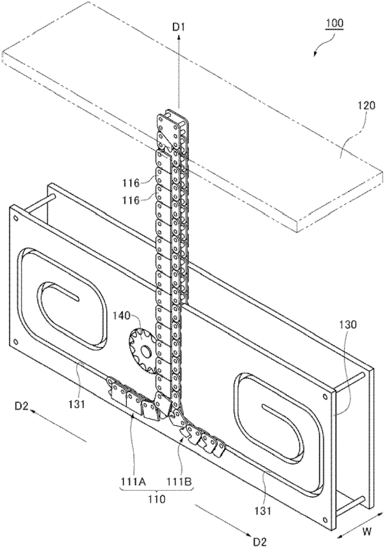
[0060] Hereinafter, the interlocking chain type lifting device 100 using the interlocking chain unit 110 for elevating drive according to one embodiment of the present invention will be described based on the drawings.

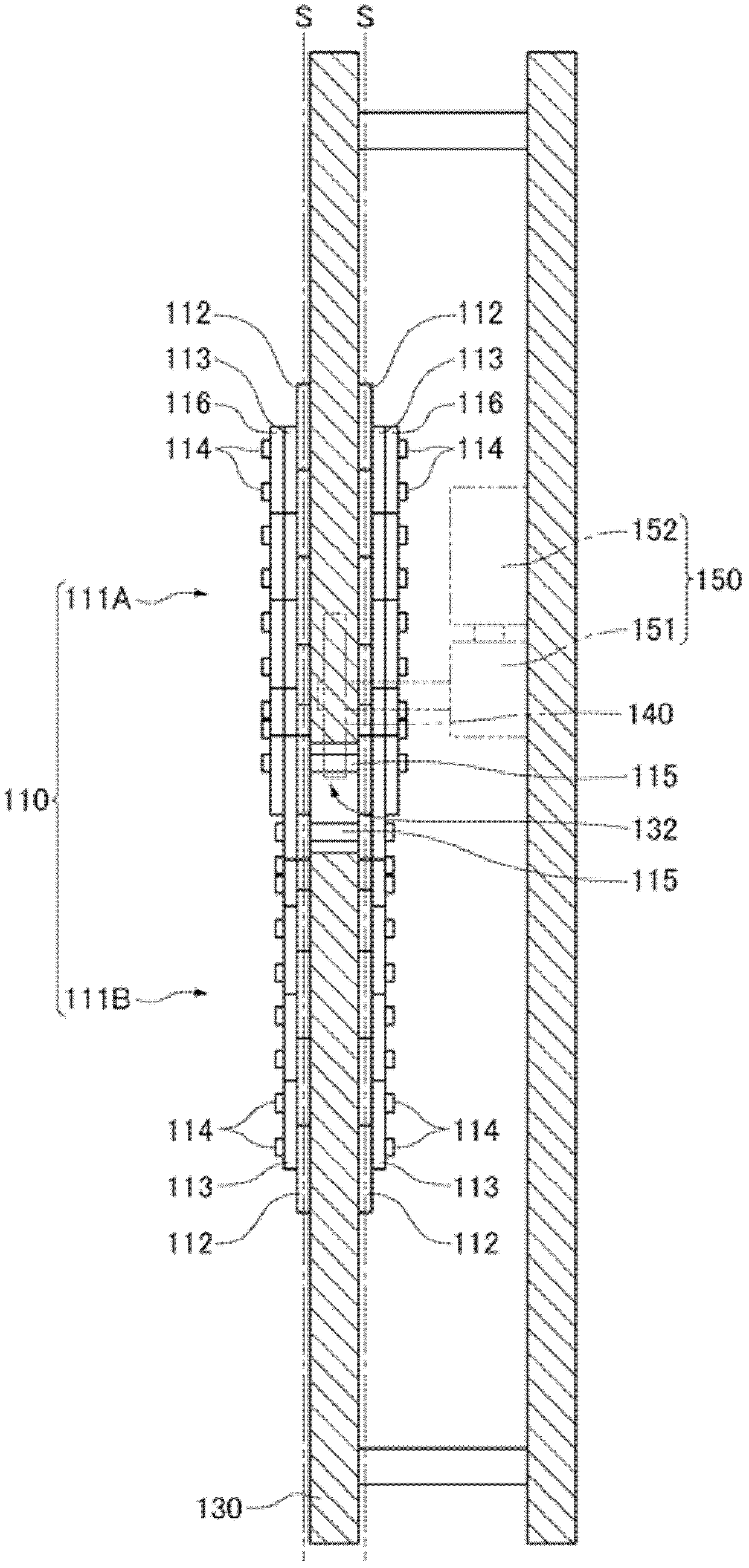
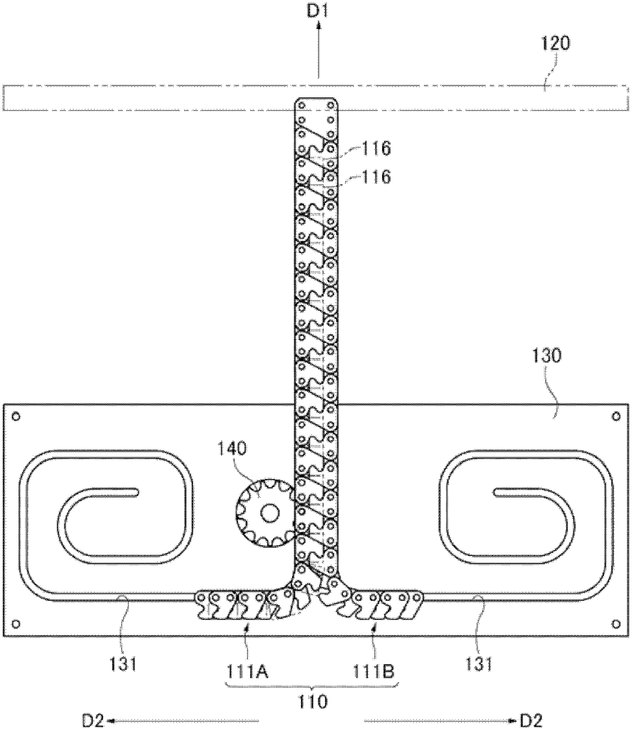
[0061] figure 1 It is an overall perspective view of the engaging chain type lifting device adopting the engaging chain unit for lifting drive according to an embodiment of the present invention; figure 2 Yes figure 1 a plan view of the engaging chain hoist shown; image 3 Yes figure 1 A front view of the engaging chain hoist shown; Figure 4 Yes image 3 An enlarged view of a part of the vicinity of the drive sprocket and the meshing chain shown; Figure 5 It is a perspective view showing the disassembled and assembled state and the disengaged state of the elevating drive meshing chain unit according to an embodiment of the present invention; Image 6 It is a front view of the engaging chain unit for lifting drive according to an embodiment of the p...


PUM


Abstract

There is provided a lifting engagement chain unit that autonomously erects a pair of engagement chains, ensures engagement accuracy between link plates and improves buckling strength. A plurality of buckling restricting attachment plates is arrayed along an outer surface of the engagement chains in a chain longitudinal direction.

Description

technical field [0001] The present invention relates to a driving device that is used in manufacturing equipment in various manufacturing fields, transfer equipment in the transportation field, nursing equipment in the medical and welfare field, stage equipment in the art field, etc., to raise and lower the driven object relative to the installation surface The lifting drive uses an intermeshing chain unit. Background technique [0002] Conventionally, there is an elevating device that rotates a drive sprocket engaged with an intermeshing chain to elevate a pair of intermeshing chains (for example, refer to Patent Document 1). [0003] like Figure 8 As shown, in a state where the flat plate end surfaces 213S facing the opposite sides of the plate engaging surfaces of the chain plates 213 contact each other obliquely with respect to the lifting direction, the engaging chains used in the above-mentioned lifting device are driven up and down, thereby driving up and down. The ...

Claims


Application Information

Patent Timeline
Patent Type & Authority Applications(China)
IPC IPC(8): F16G13/20B66F3/02
CPCB66F7/02B66F3/06F16G13/20B66F3/02B66F2700/03B66F2700/09
Inventor 生鹰道雄安藤崇尚
Owner TSUBAKIMOTO CHAIN CO
Why Eureka
Try Eureka