High pressure regulating valve

A high-pressure regulating valve and valve body technology, which is applied in the field of high-pressure regulating valves, can solve problems such as inability to accurately support the armature, inability to adjust system damping, etc., and achieve the effect of improving reliability and sealing

Inactive Publication Date: 2012-07-18
KENDRION VILLINGEN GMBH
View PDF8 Cites 3 Cited by
  • Summary
  • Abstract
  • Description
  • Claims
  • Application Information

AI Technical Summary

Problems solved by technology

Furthermore, the armature 62 cannot be supported precisely and thus the damping of the system cannot be adjusted

Method used


Image

  • High pressure regulating valve
  • High pressure regulating valve
  • High pressure regulating valve

Examples


Embodiment Construction

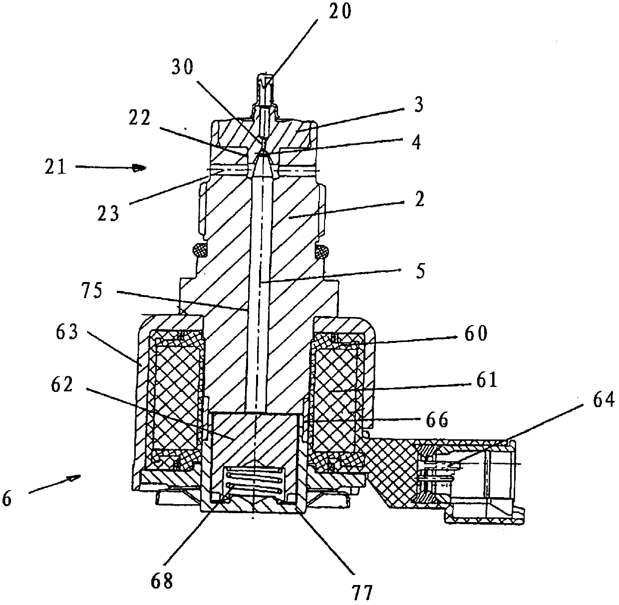
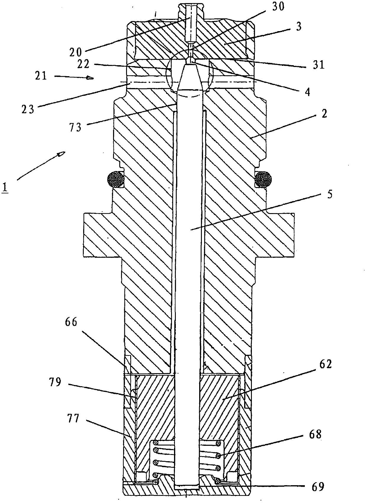
[0023] figure 1 A cross section of the high-pressure regulating valve 1 of the present invention is shown. The high-pressure regulating valve 1 is substantially formed from a valve body 2 , which is rotationally symmetrical about a longitudinal axis, with an inlet 20 and an outlet 21 . Between the inlet 20 and the outlet 21 , a valve seat 3 made of hardened steel is pressed into the valve body 2 and has a valve opening 30 connecting the inlet 20 to the outlet 21 . In the exemplary embodiment, the outlet 21 is formed in the valve body 2 by a radially extending bore 23 .

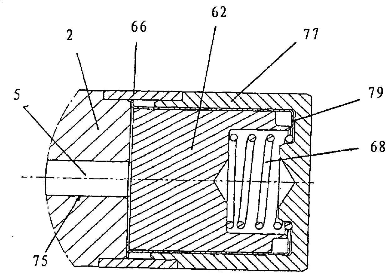
[0024] The outlet-side end of the valve bore 30 can be closed by a sealing element 4 , which is designed as a sealing ball in the present exemplary embodiment. The closing force acting on the sealing ball 4 is transmitted from the rear via the operating element 5 configured as a valve pin in the present embodiment to the operating unit 6 arranged on the valve body 2, which is configured in the present embod...


PUM


Abstract

A high pressure regulating valve (1) has a valve body (2) provided with an inlet (20) and an outlet (21), and a sealing element (4) mounted on a valve seat (3) and comprising a valve bore (30). The valve seat (3) is disposed on the valve body (2) between the inlet (20) and the outlet (21). An operating element (5) is formed along a longitudinal axis and movably supported by and suitably configured to be operated by an electromagnet (6). An armature (62) of the electromagnet (6) and the operating element (5) are executed as separate unconnected components.

Description

technical field [0001] The invention relates to a high-pressure regulating valve according to the preamble of claim 1 . Background technique [0002] Such high-pressure regulating valves are known from the prior art, for example, for pressure regulation in common-rail engines. [0003] High-pressure regulation of liquids is generally performed through ball-fit valves. They are usually controlled electromagnetically. Solenoid-operated high-pressure regulator valves of the prior art are generally constructed as follows, an example in image 3 Indicated. [0004] The high-pressure control valve 1 has a valve body 2 with an inlet 20 and an outlet 21 . Pressures of up to 2400 bar currently exist on the inlet side, for example in the field of application of common rail engines. A valve seat 3 is arranged between the inlet 20 and the outlet 21 , through which a valve opening 30 connecting the inlet 20 and the outlet 21 is guided. The valve opening 30 can be sealed off on the o...

Claims


Application Information

Patent Timeline
Patent Type & Authority Applications(China)
IPC IPC(8): F16K31/06
CPCF02M63/025F02M2200/04F02M2200/02F02M63/0052F16K31/0665F02M63/0077F02M55/025F02M63/0071F02M63/0021F02M63/0036
Inventor H·布尔卡特W·迈瓦尔德R·赫尔曼F·策拉诺R·海因格K·席斯
Owner KENDRION VILLINGEN GMBH
Why Eureka
Try Eureka