Dry heating protection control method for liquid electric heater

A technology of electric heater and control method, applied in fluid heaters, lighting and heating equipment, etc., can solve the problems of slow response of mechanical thermostat, high protection temperature, uncertain protection time, etc., to save temperature sensors, reduce The requirements of control accuracy and the effect of accurately controlling the dry burning time

Active Publication Date: 2014-07-30
深圳市北鼎晶辉科技有限公司
View PDF6 Cites 0 Cited by
  • Summary
  • Abstract
  • Description
  • Claims
  • Application Information

AI Technical Summary

Problems solved by technology

Due to the slow response of the mechanical thermostat, and the heating element itself is in the process of starting the heating, due to the thermal inertia and thermal resistance of the heating element itself, the actual temperature of the heating element is higher than that detected by the temperature sensor or the mechanical bimetal thermostat. The protection temperature is much higher, resulting in untimely protection and shortening the life of the heating element
Using a temperature sensor, due to the error of the sensor itself, the deviation of the installation position on the heating element, the process of the heating element itself, the amount of thermal paste, etc. have a great relationship, and because the temperature of the installation position is generally high, it is easy to fail. Certain risks, and increase the cost of the product
Using a mechanical thermostat, due to the slow response of the mechanical thermostat, it is difficult to solve the malfunction and timely protection at the same time
The protection time of the existing dry burning protection method is uncertain, and the protection is not timely

Method used


Image

  • Dry heating protection control method for liquid electric heater
  • Dry heating protection control method for liquid electric heater

Examples


Embodiment Construction

[0014] Below in conjunction with embodiment the present invention is further described.

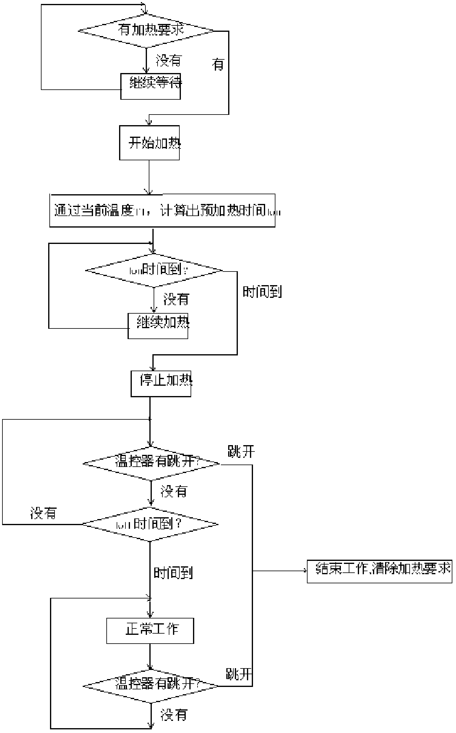
[0015] A control method for dry burning protection of a liquid electric heater, comprising the following steps:

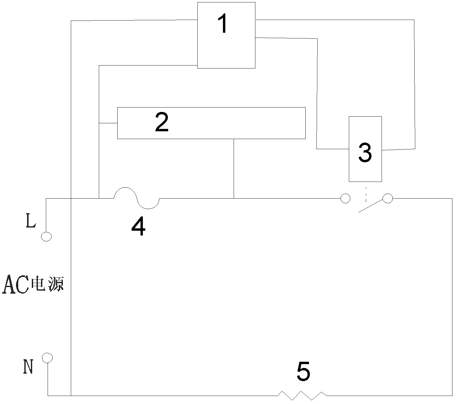
[0016] A. Install a temperature controller on the liquid electric heater, connect the temperature controller in series with the heating element of the heater and the control relay, and install a detection module at both ends of the temperature controller to detect its on-off;

[0017] B. The microprocessor is controlled by the program. When starting the liquid heater to heat, first perform a short-term heating program, that is, let the heating element of the heater heat for a short time, and then stop heating for a short time; short-time heating and stop time It is determined according to the power of the heating element itself, the volume and density of the heating element, the specific heat capacity of the heating element, and the temperature to be protected;

[0018] C. Th...


PUM


Abstract

A dry heating protection control method for a liquid electric heater relates to protection control methods for liquid electric heaters. The method includes steps: A, mounting a temperature controller on the liquid electric heater, serially connecting the temperature controller with a heater heating element and a control relay, and arranging detection modules at two ends of the temperature controller, wherein the detection module is used for detecting on and off of the temperature controller; B, allowing a microprocessor controlled by programs to perform a short-time heating program when the liquid electric heater is started for heating, namely allowing the heating element of the heater to heat in a short time and then stopping heating in a short time, wherein the heating time and the stop time are determined according to intrinsic power and the size of the heating element; and C, using the microprocessor to judge whether the liquid electric heater is in dry heating or not according to variation of on and off conditions of the temperature controller, and timely cutting off a heating power source of the heating element if the liquid electric heater is in dry heating. Using the dry heating protection control method can accurately control dry heating time, save the temperature sensor, overcome the defect that slow response of a mechanical temperature controller results in overhigh temperature of the heating element and influences the service life of the heating element, lower the requirement on control precision of the mechanical temperature controller, and reduce purchase cost of control circuit components.

Description

technical field [0001] The invention relates to small household appliances, in particular to a method for protection and control of a liquid electric heater. Background technique [0002] Existing liquid electric heaters generally use negative temperature coefficient temperature sensors, mechanical thermostats or a combination of the two to prevent dry burning. When the temperature sensed by the temperature sensor exceeds the temperature or the mechanical thermostat exceeds the temperature, the heating element is turned off to To achieve the protective effect, it is passive protection. Due to the slow response of the mechanical thermostat, and the heating element itself is in the process of starting the heating, due to the thermal inertia and thermal resistance of the heating element itself, the actual temperature of the heating element is higher than that detected by the temperature sensor or the mechanical bimetal thermostat. The protection temperature is much higher, res...

Claims


Application Information

Patent Timeline
Patent Type & Authority Patents(China)
IPC IPC(8): F24H9/20
Inventor 张默晗陈启红
Owner 深圳市北鼎晶辉科技有限公司
Why Eureka
Try Eureka