Optical compensation type long-wave infrared continuous zooming optical system

A long-wave infrared, optical system technology, applied in optics, optical components, instruments, etc., can solve problems such as image blur, achieve clear and stable imaging, low control accuracy, and large zoom ratio.

Active Publication Date: 2016-06-15
凯迈(洛阳)测控有限公司
View PDF5 Cites 4 Cited by
  • Summary
  • Abstract
  • Description
  • Claims
  • Application Information

AI Technical Summary

Problems solved by technology

[0004] The purpose of the present invention is to provide an optical compensation type long-wave infrared continuous zoom optical system, which is used to solve the problem that the mechanical compensation optical system tends to blur some images during the zoom process

Method used


Image

  • Optical compensation type long-wave infrared continuous zooming optical system
  • Optical compensation type long-wave infrared continuous zooming optical system
  • Optical compensation type long-wave infrared continuous zooming optical system

Examples


Embodiment Construction

[0028] The present invention will be described in further detail below with reference to the accompanying drawings.

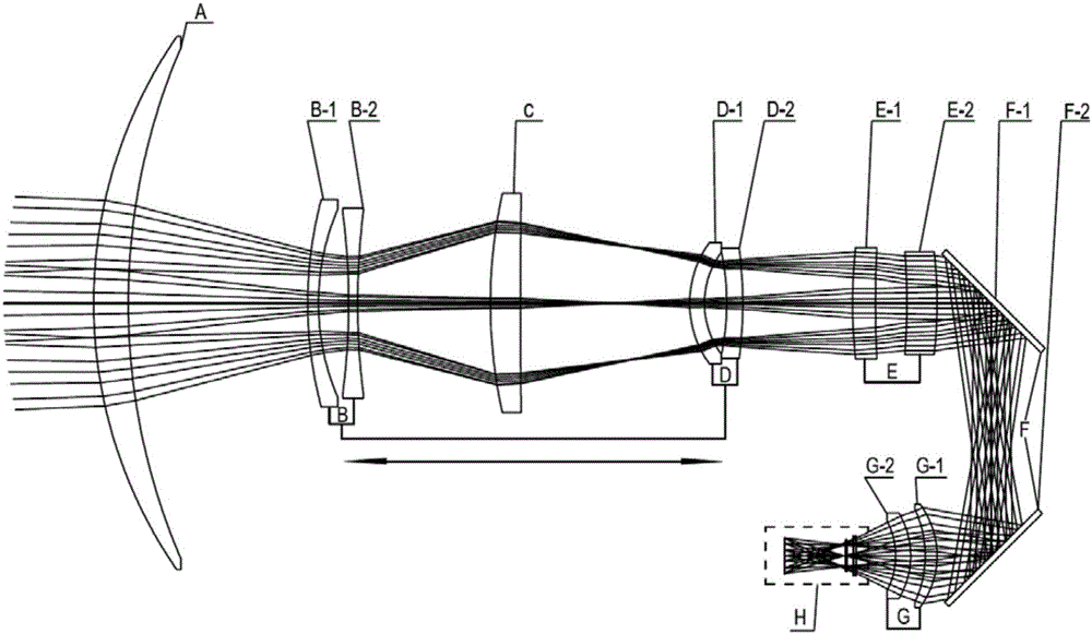
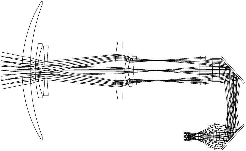
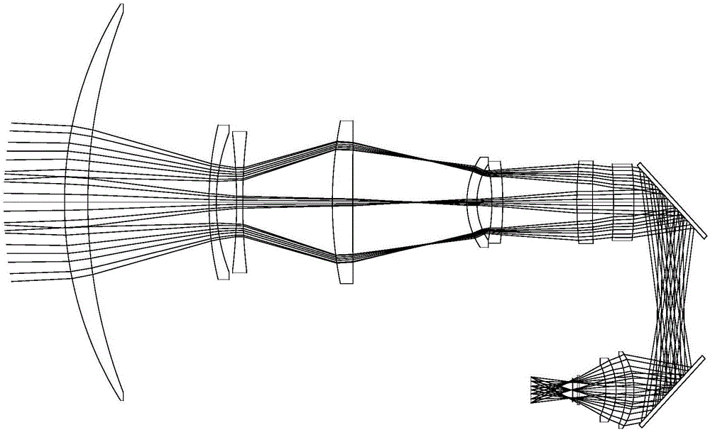
[0029] The optical compensation long-wave infrared continuous zoom optical system provided by the present invention includes a front fixed mirror group, a front movable mirror group, a middle fixed mirror group, a rear mobile mirror group and a rear fixed mirror group arranged in sequence from the object side to the image side. The positions of the front fixed mirror group, the middle fixed mirror group and the rear fixed mirror group are constant, and the distance between the front moving mirror group and the rear moving mirror group is also kept constant. During the zooming process, the front moving mirror group and the rear moving mirror group are linked on the optical axis at equal intervals, at the same speed, and in the same direction.

[0030] Both the front moving mirror group and the rear moving mirror group are composed of two lenses, wherein the fron...


PUM


Abstract

The invention relates to an optical compensation type long-wave infrared continuous zooming optical system, the system comprises a front fixed lens set, a front movable lens set, a middle fixed lens set, a rear movable lens set and a rear fixed lens set, the front movable lens set is formed by a first movable lens and a second movable lens arranged in sequence, the rear movable lens set is formed by a third movable lens and a fourth movable lens arranged in sequence, and the front movable lens set and the rear movable lens are ganged forward and backward with equal interval, equal speed and same direction to realize optical compensation type continuous zooming. The optical compensation type system has a simple structure which is easy to manufacture, and has relatively low precision requirement for controlling the system. A shortcoming that a mechanical compensation system needs precise cooperation of a complex cam structure or double leading screws to ensure image keeping clear in zooming process is overcome.

Description

technical field [0001] The invention relates to an optical compensation type long-wave infrared continuous zoom optical system. Background technique [0002] Infrared imaging system has the advantages of all-weather work and no auxiliary lighting, and has been widely used in military fields such as warning, reconnaissance and guidance. For military equipment, usually the main targets on the ground are ground bunkers, factories, dams, tanks, armored transport vehicles, cars and soldiers. The surface temperature of these targets is generally not high, the radiation energy is small, and the peak of thermal radiation is concentrated in the long-wave infrared band. In addition, in the process of atmospheric transmission, infrared is easily absorbed by substances, but for mist, long-wave infrared is easier to pass through. In this way, compared with medium-wave (3μm ~ 5μm) infrared, long-wave infrared imaging systems can be used at lower temperatures. Make the most effective det...

Claims


Application Information

Patent Timeline
Patent Type & Authority Applications(China)
IPC IPC(8): G02B15/15G02B1/00G03B17/17
CPCG02B15/15G03B17/17G02B1/00
Inventor 吴海清赵新亮李萍田海霞崔莉李同海
Owner 凯迈(洛阳)测控有限公司
Why Eureka
Try Eureka