Control device for cover of electric induction furnace

A control device and furnace cover technology, applied in furnaces, furnace components, lighting and heating equipment, etc., can solve problems such as large heat loss

Inactive Publication Date: 2012-07-18
KEHUA HLDG
View PDF6 Cites 7 Cited by
  • Summary
  • Abstract
  • Description
  • Claims
  • Application Information

AI Technical Summary

Problems solved by technology

In addition to the feeding time of the induction furnace, the temperature in the furnace can reach above 1600oC during the process of melting molten

Method used


Image

  • Control device for cover of electric induction furnace
  • Control device for cover of electric induction furnace
  • Control device for cover of electric induction furnace

Examples


Example Embodiment

[0025] Specific implementation method

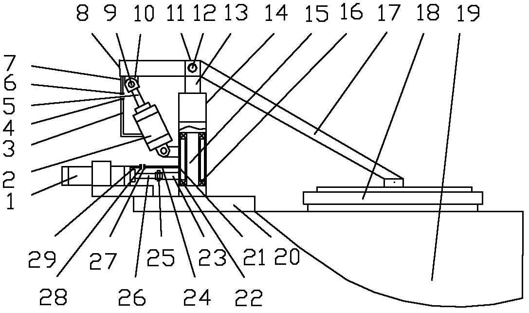
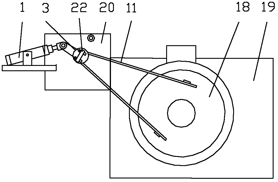
[0026] The embodiments shown in the accompanying drawings are as follows: a pneumatic control device for the furnace cover of an induction electric furnace.

[0027] like figure 1 , figure 2 Shown: frame 20 is installed on one side of body of heater 19. Vertical shaft 15 is housed in framework 20 middle parts. A sleeve 14 is sheathed on the outside of the vertical shaft 15 . A bearing 16 is installed between the vertical shaft 15 and the sleeve 14 , and the sleeve 14 can rotate around the vertical shaft 15 through the bearing 16 . A connecting rod I13 is welded on the upper end of the sleeve 14, and the upper part of the connecting rod I13 is movably connected with the connecting rod 12 through a pin shaft I12. One end of the connecting rod 12 is an inclined oblique rod 17, and the end of the inclined oblique rod 17 is fixedly connected with the large furnace cover 18. The other end of the connecting rod 12 is a transverse conn...


PUM


Abstract

The invention relates to a control device for a cover of an electric induction furnace. A framework with a vertical shaft in the middle is arranged on one side of a furnace body, a sleeve is installed outside the vertical shaft through a bearing in sleeve mode, a connection rod is installed at the upper end of the sleeve through a connecting rod I and a pin shaft I, a lifting cylinder is installed between the sleeve and the connection rod, and the connection rod is further connected with a big furnace cover. Two limiting contact blocks of a limiting switch X2 are further installed between a lifting cylinder tube body and the connection rod, a rotary cylinder is further installed on the framework, a piston rod of the rotary cylinder is connected with the sleeve through a pin shaft III and a connecting rod V, and two limiting contact blocks of a limiting switch X1 are further installed between the rotary cylinder tube body and the sleeve. A high-pressure air pump is respectively communicated with the lifting cylinder and a front air chamber and a rear air chamber of the rotary cylinder through a solenoid directional valve DTI and a solenoid directional valve DTII, and a 220-volt alternate current power source is respectively electrically connected a first return circuit, a second return circuit, a third return circuit, a fourth return circuit, a fifth return circuit and a sixth return circuit through an L connection point and an N connection point. The control device for the cover of the electric induction furnace can open and close the furnace cover safely and conveniently,can greatly reduce loss of heat energy and greatly reduces casting cost.

Description

technical field [0001] The invention relates to a control device, in particular to a control device for the cover of an induction electric furnace for melting molten iron in the foundry industry. Background technique [0002] The heating furnaces for melting molten iron in the foundry industry are classified into two types of cupola furnaces and electric furnaces according to the heat source, and the electric furnaces are the most widely used medium frequency induction furnaces. The domestic induction furnace is also equipped with a furnace cover, but because it is relatively heavy and inconvenient to move, many electric furnaces have a furnace cover and do not use it. The furnace cover of the imported induction furnace uses a set of hydraulic cylinders to control the opening and closing of the furnace cover (including lifting and rotating actions). In addition to the feeding time of the induction furnace, the temperature in the furnace can reach above 1600oC during the pro...

Claims


Application Information

Patent Timeline
IPC IPC(8): F27D1/18
Inventor 张笑山
Owner KEHUA HLDG
Why Eureka
Try Eureka