Optical encoder

A technology of optical encoders and optical disks, applied in the field of optical encoders, can solve the problems of limited optical encoder application range, short service life, poor temperature resistance limit, etc., and achieve the goal of increasing light utilization, increasing life, and reducing brightness Effect

Active Publication Date: 2015-01-07
AU OPTRONICS CORP
View PDF5 Cites 0 Cited by
  • Summary
  • Abstract
  • Description
  • Claims
  • Application Information

AI Technical Summary

Problems solved by technology

Although optical discs made of metal and glass have good temperature resistance and long service life, optical discs formed by electroforming and etching processes require high manufacturing costs
In addition, compared with optical discs made of metal and glass, the light source in the optical encoder (such as a light emitting diode) has a shorter service life and a poorer temperature limit. Therefore, the type of light source used often limits the optical Encoder application range

Method used


Image

  • Optical encoder
  • Optical encoder
  • Optical encoder

Examples


Embodiment Construction

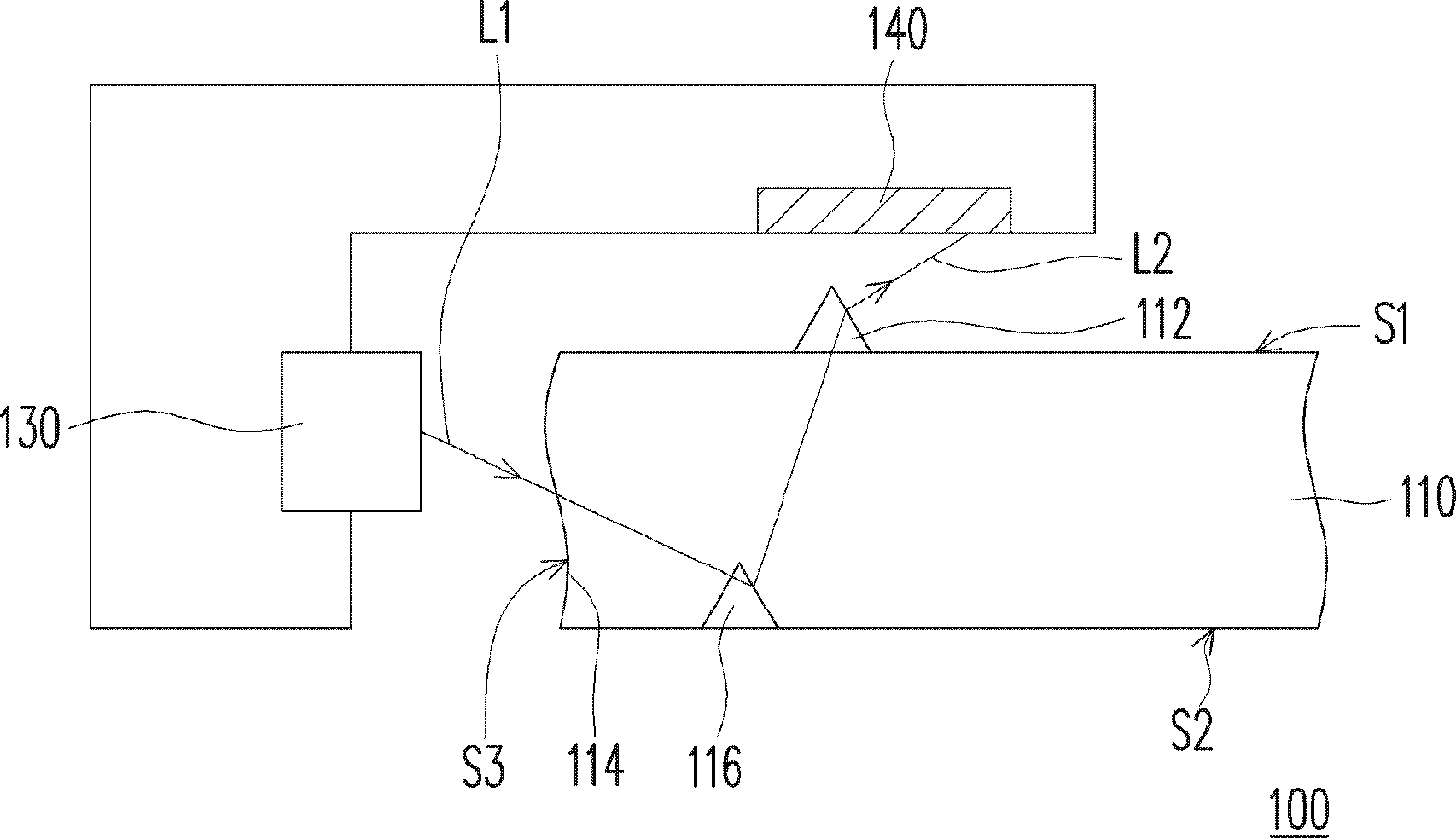
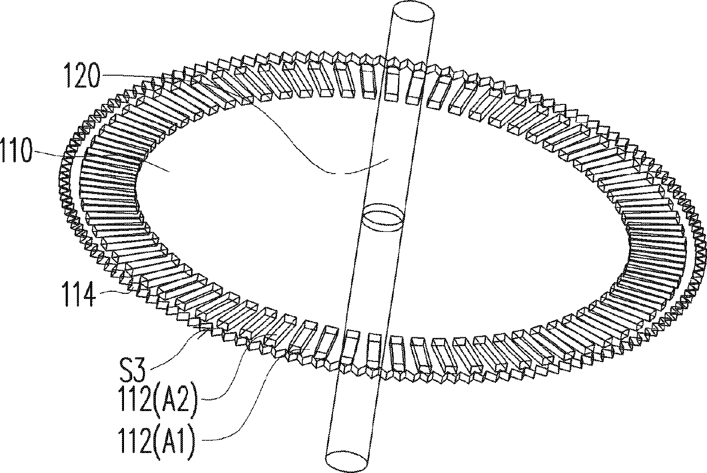
[0051] Figure 1A It is a schematic side view of the optical encoder according to the first embodiment of the present invention. Figure 1B for Figure 1A Schematic top view of a medium optical disc.

[0052] Please refer to Figure 1A and Figure 1B , the optical encoder 100 of this embodiment includes an optical disk 110 , a shaft 120 , a light source 130 and a sensor 140 . In this embodiment, the optical disc 110 is, for example, a disk-shaped optical disc. In addition, the material of the optical disk 110 is, for example, polycarbonate (PC), acrylic (Polymethyl methacrylate, PMMA) or dacron (polyethylene terephthalate, PET) and other transparent polymer materials. Specifically, the optical disc 110 has a first surface S1, a second surface S2 opposite to the first surface S1, a side surface S3 connected between the first surface S1 and the second surface S2, and a plurality of The first optical structure 112 of S1.

[0053]In addition, the optical disk 110 further inclu...


PUM


Abstract

The invention provides an optical encoder, including an optical disc, a shaft, an optical source and a sensor. The optical disc possesses a first surface, a second surface opposite to the first surface, a side surface connected between the first surface and the second surface, and a plurality of optical optical structures arranged on the first surface. The shaft is arranged at the center of the optical disc, wherein the optical disc is rotated with the shaft as the center. The optical source is arranged at one side of the side surface, wherein the optical source provides rays which is transmitted toward the surface. The sensor is arranged at one side of the optical disc to receive rays emitted from the first surface, wherein the first surface is positioned between the second surface and the sensor.

Description

【Technical field】 [0001] The present invention relates to an optical encoder, and more particularly to an optical encoder with an optical disc having an optical structure. 【Background technique】 [0002] At present, in order to accurately grasp the rotation of the motor, an optical encoder is installed inside the motor in the prior art. An optical encoder is composed of an optical disk engraved with specific information, a light source and a light sensor. Generally speaking, the optical disc has a plurality of periodically arranged openings that allow light to pass through. When the optical disc rotates, the optical sensor will receive a specific periodic optical signal. At this time, the optical encoder can According to this optical signal, the rotational speed and rotation amount of the motor are judged. [0003] In existing optical encoders, the optical disk is usually made of metal or glass, and the metal optical disk is formed by electroforming, and the openings on th...

Claims


Application Information

Patent Timeline
Patent Type & Authority Patents(China)
IPC IPC(8): G01D5/347
Inventor 刘康仲许良伊吕学宪
Owner AU OPTRONICS CORP
Why Eureka
Try Eureka