Heavy oil thermal recovery casing pipe testing device

A heavy oil thermal recovery casing and testing device technology, which is applied in the direction of measuring devices, fluid tightness testing, machine/structural component testing, etc. Thermal expansion and other issues to achieve the effect of increasing reliability and ensuring safe use

Inactive Publication Date: 2012-07-18
BC P INC CHINA NAT PETROLEUM CORP +1
View PDF3 Cites 19 Cited by
  • Summary
  • Abstract
  • Description
  • Claims
  • Application Information

AI Technical Summary

Benefits of technology

This technology uses repetitive heat-cool cycles that mimic how an existing drilling rig works at high temperatures for recovering bitumen from subterranean formations. By doing this it helps predict what happens when there are more severe environmental factors like temperature or pressure changes over time compared with older methods such as static loading analysis (SCA). It also allows researchers to study different types of materials used during production without having to actually set up them downstream on site. Overall, these technical improvements make better understanding about the properties of cased boreholes made by various techniques including steam injection into hot water flood reservoirs improving their effectiveness against stress corrosion crackings caused by cyclical variations in surrounding pressurized fluids.

Problems solved by technology

Technological Problem: Existing thermal recovery testing for simulating the repetitive temperature change caused by injecting fluid into an underground reservoir requires large equipment that can be expensive or difficult to install at different locations within the reservior. Additionally, current simulations only model the effects of pressure loading during initial stages but neglect any other factors like strain hardening which may occur over time due to cycling between temperatures.

Method used


Image

  • Heavy oil thermal recovery casing pipe testing device
  • Heavy oil thermal recovery casing pipe testing device

Examples


Embodiment Construction

[0012] The present invention will be further described in detail below in conjunction with specific embodiments, and the given examples are only for clarifying the present invention, not for limiting the scope of the present invention.

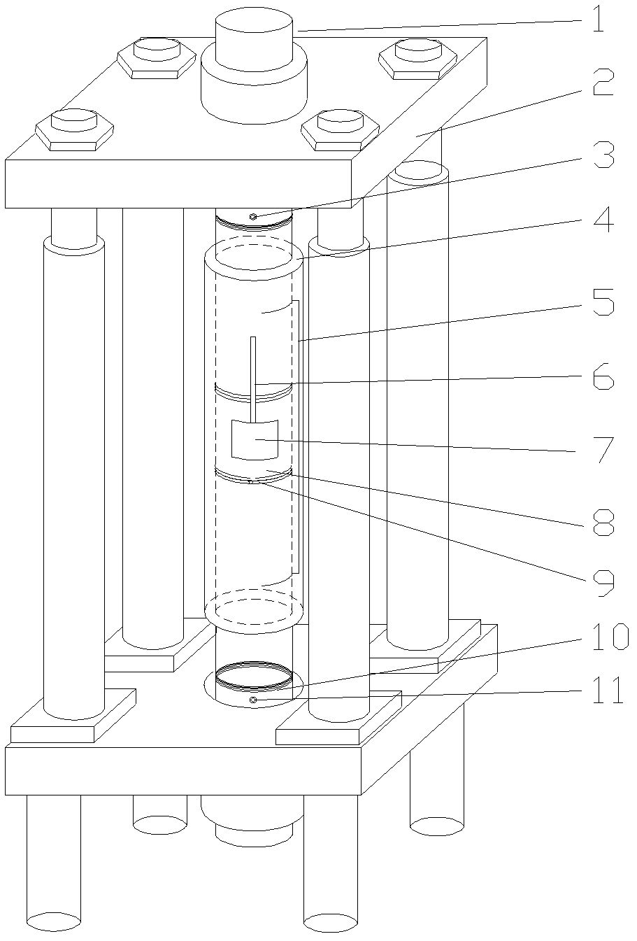
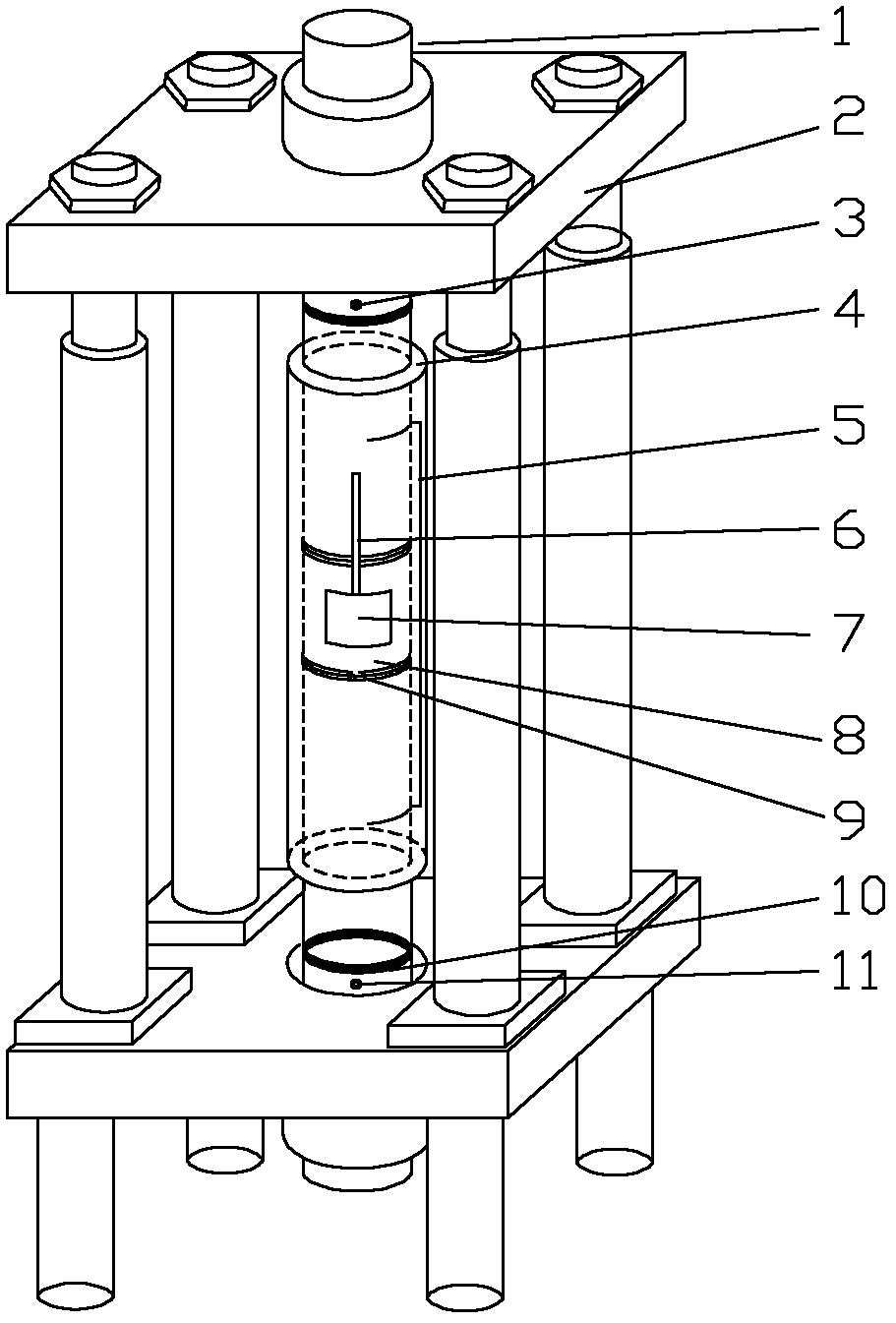
[0013] see figure 1 , the embodiment of the present invention provides a heavy oil thermal recovery casing testing device, which specifically includes the following components:

[0014] The mark 1 in the figure is the auxiliary rod, which plays the role of connecting the casing and the axial loading device 2, and at the same time plays the role of sealing the pipe end for the airtight test; 4 is the openable electric heating furnace, the electric heating furnace Wrapped on the surface of the casing, the electric heating furnace can wrap 3 / 4 of the length of the sample to increase the heat-affected area of ​​the sample, and more effectively simulate the heating of the casing. Close the electric heating furnace when heating, and open the furnac...


PUM


Abstract

The invention discloses a heavy oil thermal recovery casing pipe testing device, belonging to wellhead control mechanical equipment. The testing device comprises a casing pipe, an assisting rod, a pressurization pipeline, a loading device, a heating device, a displacement sensor, a thermocouple, a leak collecting device and an internal pressure sensor, wherein the leak collecting device is arranged on the outer surface of a coupling of the casing pipe, the casing pipe is connected with the loading device by the assisting rod, the internal pressure sensor is connected with the pressurization pipeline by the assisting rod, the heating device is wrapped on the surface of the casing pipe, the two ends of the displacement sensor are fixed at the two ends of the casing pipe by fixing devices, and the thermocouple is fixed on the casing pipe by a hose clamp. With the adoption of the mode of repeated temperature rising and dropping, the testing device can effectively simulate the true situation of the service of the casing pipe in a heavy oil thermal recovery well and can perform accurate evaluation on the applicability of the casing pipe.

Description


Claims


Application Information

Patent Timeline
Owner BC P INC CHINA NAT PETROLEUM CORP
Why Eureka
Try Eureka