

Detection circuit for monitoring state of current transformer
A transformer and state technology, applied in the direction of measuring current/voltage, measuring electrical variables, voltage/current isolation, etc., can solve problems affecting the normal output signal of the current signal acquisition circuit, reduce the current measurement accuracy of the smart circuit breaker, etc., and achieve simplification Hardware circuit, improved current measurement accuracy, high safety and reliability effects
- Summary
- Abstract
- Description
- Claims
- Application Information
AI Technical Summary
Problems solved by technology
Method used
Image

Examples
Embodiment 1
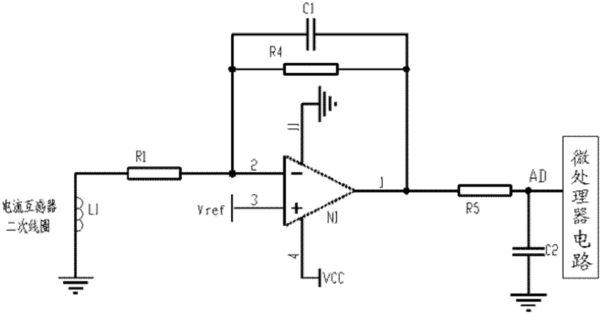
[0016] Embodiment 1: A detection circuit for monitoring the state of a current transformer, comprising a first resistor, a fourth resistor, a fifth resistor, a first capacitor, a second capacitor, and a first amplifier; one end of the first resistor is connected to the current transformer, and the other One end is connected to the negative input end of the first amplifier; one end of the fourth resistor is connected to the negative input end of the first amplifier, and the other end is connected to the output end of the first amplifier; one end of the fifth resistor is connected to the output end of the first amplifier, and the other end is connected to the microprocessor circuit; One end of the first capacitor is connected to the negative input end of the first amplifier, and the other end is connected to the output end of the first amplifier; one end of the second capacitor is connected to the ground, and the other end is connected between the fifth resistor and the microproce...
Embodiment 2
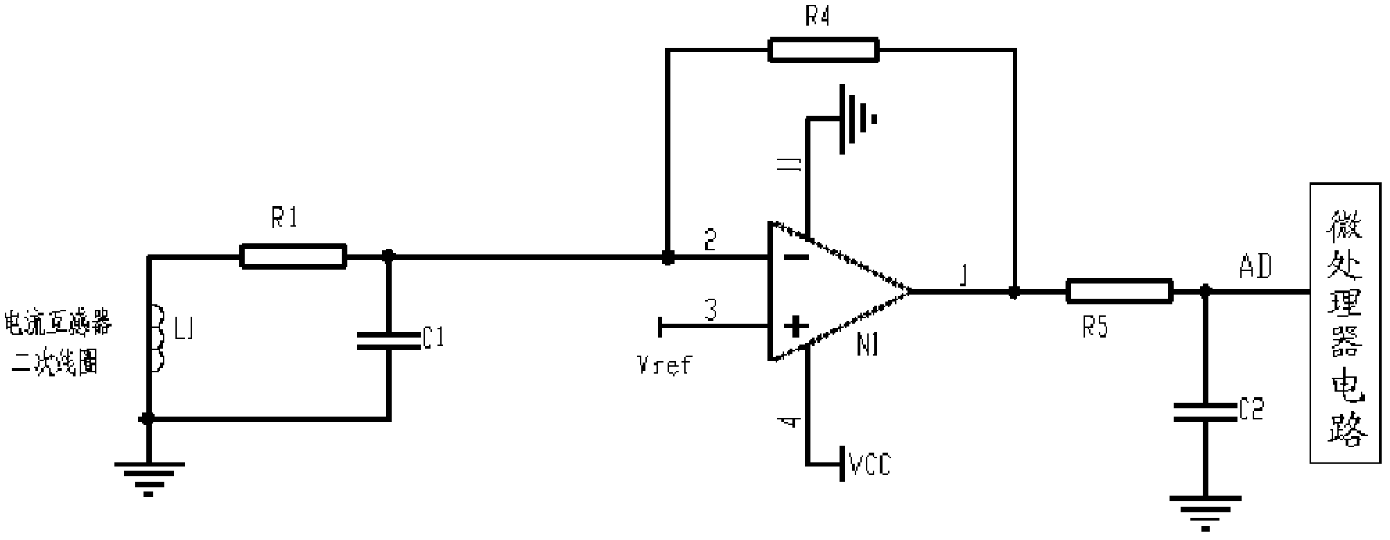
[0019] Embodiment 2: A detection circuit for monitoring the state of a current transformer, comprising a first resistor, a fourth resistor, a fifth resistor, a first capacitor, a second capacitor, and a first amplifier; one end of the first resistor is connected to the current transformer, and the other One end is connected to the negative input end of the first amplifier; one end of the fourth resistor is connected to the negative input end of the first amplifier, and the other end is connected to the output end of the first amplifier; one end of the fifth resistor is connected to the output end of the first amplifier, and the other end is connected to the microprocessor circuit; One end of the first capacitor is connected to the negative input end of the first amplifier, and the other end is grounded; one end of the second capacitor is connected to the ground, and the other end is connected between the fifth resistor and the microprocessor circuit; the positive input end of th...
Embodiment 3
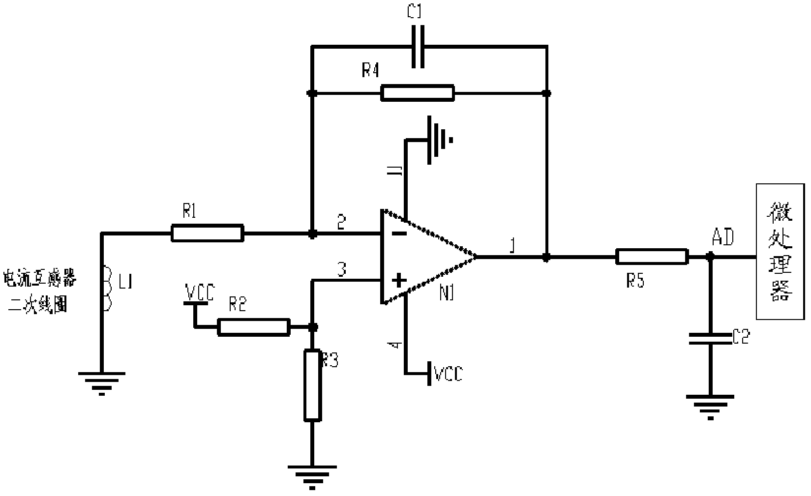
[0022] Embodiment 3: A detection circuit for monitoring the state of a current transformer, comprising a first resistor, a second resistor, a third resistor, a fourth resistor, a fifth resistor, a first capacitor, a second capacitor, and a first amplifier; One end of the resistor is connected to the current transformer, and the other end is connected to the negative input end of the first amplifier; one end of the second resistor is connected to the power supply, and the other end is connected to the positive input end of the first amplifier; one end of the third resistor is grounded, and the other end is connected to the positive input end of the first amplifier; One end of the fourth resistor is connected to the negative input end of the first amplifier, and the other end is connected to the output end of the first amplifier; one end of the fifth resistor is connected to the output end of the first amplifier, and the other end is connected to the microprocessor; one end of the...
PUM
 Abstract
Description
Claims
Application Information